|
|
Object Silhouette  : Options and Results


Access: Open this function from the following location:
-
Select Wireframe > Derived Curves > Object Silhouette from the menu bar.
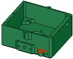
Create a 2D inner and/or outer silhouette (perimeter curve) of objects.
In addition, the function allows the projection of a localized section of the parameters.
Required Step 1 
- Pick one or more objects from which the silhouette is to be created.
- Click <Exit><Exit> to proceed to the next step.
Required Step 2 
-
Set the parameters. Depending on the main parameter option selected, pick the appropriate entity:
-
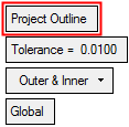
For the Project Outline option: Pick the projection plane. This can be a plane, planar face, or a UCS (XY) on which the silhouette will be created. The plane sets the normal direction for the extreme outer and inner silhouette of the part and also the position of the curve.
-
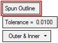
For the Spun Outline option: Pick the axis of revolution. This can be an axis, line, 2 points, arc, cone face, or UCS axis around which the silhouette will be created.
The following parameters are displayed.

Parameters
Project Outline /
Spun OutlineThis toggle option enables you to define either a projection plane or an axis of revolution.
Project Outline
Pick the projection plane on which the silhouette will be created.
Spun Outline
Pick the axis of revolution. This can be an axis, line, 2 points, arc, cone face, or UCS axis around which the silhouette will be created.
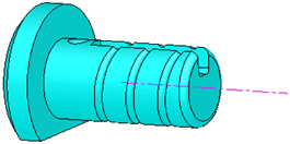
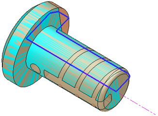
Some objects have basically a revolved shape with extra features that do not enable a simple silhouette contour to be defined. This silhouette contour is required to define the revolved shape.
The Revolve option defines the silhouette contour on a plane that goes through the selected axis. When the axis is not in the Z direction, the plane is in the Z direction; when the axis is in the Z direction, the plane is in the X direction. The silhouette contour revolved by 360 degrees around the axis defines the revolved shape.
Note: The revolved shape will give the minimum stock for an NC lathe machine. Any other features of the required shape can then be produced by NC milling procedures.
Basically a revolved shape with extra features.
The silhouette contour revolved by 360 degrees around the axis defines the revolved shape.
Tolerance
Set the tolerance value to improve the accuracy of the silhouette projection. This defines the limit that the silhouette curve can deviate from the projection of the selected object(s). The default is 0.01mm (0.0004 inch).
Outer & Inner /
Outer /
InnerThis is a dropdown list of entities to be included in the silhouette:
Outer & Inner
Include the outer and inner curves of the selected object(s). This is the default option. See the examples below.
Outer
Include only the outer curves of the selected object(s). See the examples below.
Inner
Include only the inner curves of the selected object(s). See the examples below.
Global option results with the silhouette created on the plane of the face selected in the above imageabove image
Outer & Inner
Outer
Inner
Global option results with the silhouette created on a selected planeplane 
Outer & Inner
Outer
Inner
Global /
LocalThis toggle option enables you to define which entities are included in the silhouette.
Global
Create a silhouette of the entire object(s). This is the default option.
ExampleExampleSilhouette result
Local
Create a silhouette of a localized section. This allows you to limit the silhouette to the portion of the part either above or below the selected plane.
When this option is selected, an Offset parameter and a directional arrow is displayed enabling you to set the direction of the silhouette to limit the silhouette to the portion of the part either above or below the selected plane.
ExampleExampleLocal option - Offset = 20
Result
Local option - Offset = 0
Result
-
-
Click OKOK
 or ApplyApply
 in the Feature Guide to complete the function.
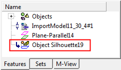
When completed, the Object Silhouette feature will appear in the Feature Tree.

|