Coordinate Label PMI 

Access: Open this function from one of the following locations:
-
Click the
button in the toolbar. -
Select Tools > PMI > Coordinate Label from the menu bar.
Create PMI Coordinate Label symbols and assign them to appropriate entities.
These labels call out selected points and give the X, Y, and Z dimensions from a UCS origin. The PMI-based coordinate labels can be created in either parts or assemblies. Like all PMI, the coordinate labels can also be displayed in drafting views.
Once the PMI Coordinate Label symbols have been created (in the Modeling environment), they can be listed in the Automatic Coordinate Table (in the Drafting environment).
|
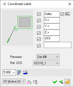
The dialog for the symbol is displayed.
|
The image below shows an example of the symbol with each element labeled.
|
|
|
|
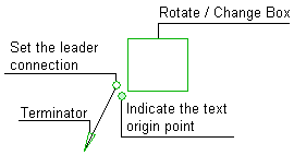
The procedure below describes how to create this symbol in Cimatron.
For a description of the symbol elements in this dialog, see the Dialog Structure.
Leader/Symbol Creation Order:Leader/Symbol Creation Order:
When adding a symbol, the creation order of the symbol location and leader are defined as follows:
Adding a free symbol: When adding a symbol (without first selecting an entity), the first click defines the symbol location and the second click creates the leader.
Adding a symbol to a selected entity: When adding a symbol to a selected entity, the first click creates the leader and the second click defines the symbol location.
Working with PMI Coordinate Label
Coordinate Labels that can be created in the Drafting environment can also be created using the PMI Coordinate Label function.
To add a PMI Coordinate Label symbol:
-
InvokeInvoke the PMI Coordinate Label tool. A default, grayed-out PMI Coordinate Label dialog is initially displayed.
-
Pick the entity to be annotated.
|
The part before an entity is picked. |
The part after an entity is picked. |
|
|
|
After you pick the entity, a transparent plane is displayed. This is the plane that the PMI symbol and annotation will be created on; it is parallel to the XY plane of the active UCS, and its Z coordinate traverses the picked point or the start point of the picked edge.
-
Position the Coordinate Label symbol by picking a location on the screen.
|
The Coordinate Label symbol is displayed in the default orientation onto the plane. |
Display and orientate the label as required (using the options available in the PMI Coordinate Label dialog shown above); in this case, Box -Off and an angle of 90° was selected. |
|
|
|
Notes:
-
The Coordinate Label is created in the plane indicated in the bottom-left corner of the PMI Coordinate Label dialog and is associated with the picked entity. See PMI Associativity below.
-
The "Index" text and the index number checkboxes can be selected independently of one another. The resulting PMI is displayed as follows:
|
The "Index" text and number are displayed: |
Only the "Index" text is displayed: |
|
|
|
|
Only the index number is displayed: |
No index information is displayed: |
|
|
|
-
Edit the Coordinate Label parameters with the help of the dialog hot spots and tips (change/rotate box, terminator, etc. - see above). Change font style and character size also if required.
-
Re-position the symbol/annotation, if required, either by picking another location or by dragging it to the new location.
-
Close the PMI Coordinate Label dialog by clicking the appropriate approval option (or by clicking the MMBMMB anywhere outside of the dialog).
|
|
OK: Accept the changes, perform the operation, and close the current dialog/task. |
|
|
Apply: Accept the changes, perform the operation, and keep the current dialog/task open. |
|
|
Cancel: Cancel all changes and close the dialog/task without saving the settings. |
Note: The automatic coordinate label parameters constitute unique symbolic text. They can be edited in the Text Editor but their source data cannot be changed.
Edit or re-position a symbol after creation
Double-click the appropriate symbol. The relevant dialog associated with the symbol is displayed. This means that you are now in edit mode.
Edit the symbol elements and/or re-position the symbol as required.
PMI Associativity
A PMI is fully associated with the model - changing the model shape is reflected automatically in the PMI. A PMI that loses associativity remains in its last position and changes color.