|
|
Dimension PMI 

Access: Open this function from one of the following locations:
-
Click the
button in the toolbar. -
Select Tools > PMI > Dimension from the menu bar.
Create PMI Dimension symbols and assign them to appropriate entities.
|
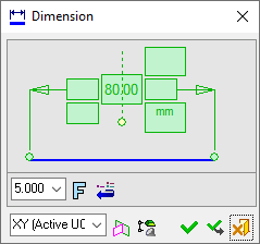
The dialog for the symbol is displayed.
The symbol dialog is initially displayed grayed out until the symbol is positioned in the graphics window.
|
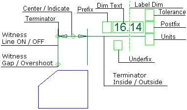
The image below shows an example of the symbol with each element labeled.
|
|
|
|
The procedure below describes how to create this symbol in Cimatron.
Annotate the symbol either in the dialog or in the graphics window (once the symbol has been positioned).
For a description of the symbol elements in this dialog, see the Dialog Structure.
Leader/Symbol Creation Order:Leader/Symbol Creation Order:
When adding a symbol, the creation order of the symbol location and leader are defined as follows:
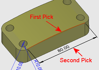
Adding a free symbol: When adding a symbol (without first selecting an entity), the first click defines the symbol location and the second click creates the leader.
Adding a symbol to a selected entity: When adding a symbol to a selected entity, the first click creates the leader and the second click defines the symbol location.
To add a PMI Dimension symbol:
-
InvokeInvoke the PMI Dimension tool. A default, grayed-out PMI Dimension dialog is initially displayed.
-
Pick the entity to be dimensioned.
|
The part before an entity is picked. |
The part after an entity is picked. |
|
|
|
After you pick the entity, a transparent plane is displayed. This is the plane on which the PMI symbol and annotation will be created; it is parallel to the XY plane of the active UCS and its Z coordinate traverses the picked point or the start point of the picked edge.
Although the picked entity is a 3D edge, its projection on the plane is a full circle.
-
Position the dimension by picking a location on the screen.
The default PMI Dimension dialog that was initially displayed when you invoked the dimension tool now changes to a dimension dialog specific to the type of entity being dimensioned. In this case, a diameter dimension dialog. After positioning the dimension, the appropriate PMI dimension dialog is displayed:
|
|
Note: The Dimension symbol is created in the plane indicated in the bottom-left corner of the PMI Dimension dialog and is associated with the picked entity. See PMI Associativity below.
-
Edit the Dimension parameters, if required, as explained in Dimension in the Drafting environment.
-
Re-position the symbol/annotation, if required, either by picking another location or by dragging it to the new location.
-
Close the PMI Dimension dialog by clicking the appropriate approval option (or by clicking the MMBMMB anywhere outside of the dialog).
|
|
OK: Accept the changes, perform the operation, and close the current dialog/task. |
|
|
Apply: Accept the changes, perform the operation, and keep the current dialog/task open. |
|
|
Cancel: Cancel all changes and close the dialog/task without saving the settings. |
The following PMI dimensions can currently be created. (In each if these cases, after you have picked the required entities, position the dimension by picking a point on the screen.)
Linear dimensionLinear dimension
Radial dimensionRadial dimension
Angular dimensionAngular dimension - (exactly as in the Drafting environment) by picking two edges
Chamfer dimensionChamfer dimension - by picking three edges
To edit (or to re-position) a symbol after it has been created:
Double-click the appropriate symbol. The relevant dialog associated with the symbol is displayed. This means that you are now in edit mode.
Edit the symbol elements and/or re-position the symbol as required.
PMI Associativity
A PMI is fully associated with the model - changing the model shape is reflected automatically in the PMI. A PMI that loses associativity remains in its last position and changes color.
|