|
|
Cutter Tilt Control
Tilting enables you to use the full capabilities of your 5-axis machine to mill additional material with the current tool. Instead of immediately replacing the cutter when a gouge is imminent, the work table or tool is tilted to a specified Tilt Angle, enabling you to continue removing material with the current tool.
The Cutter Tilt Control branch enables you to define the level of control over its use and over the display of the parameters in the branch. The following branch options are available: On and Off. Off is the default option.
Branch option: On
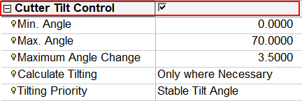
For a parameter description, click on a parameter in the dialog image below.
Depending on the procedure and your parameter settings, some parameters may not be available or other parameters may be displayed.
|
Dialog when accessed from one of the following procedures: |
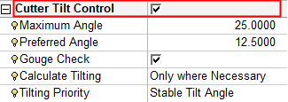
Dialog when accessed from the Convert to 5X procedure. |
|
|
|
|
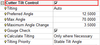
Dialog when accessed from the Convert to 5X > Auto 5X Tilt procedure. |
|
 |
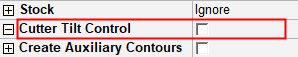
Branch option: Off
The default option for this branch is No. This means that there is no cutter tilting.
Notes:
-
Cutter Tilt Control is only displayed if the toolpath is 5-axis.
-
To use the Cutter Tilt Control parameters, a ball cutter (not-conic) with a holder must be defined for the procedure. The Cutter Tilt Control parameters cannot be used if a conic cutter is defined.
General Notes about Parameter Tables
Convert to 5X Operational NotesConvert to 5X Operational Notes
To use the Convert to 5X > 5X Tilt procedure, the following are the prerequisites and operational requirements:
Prerequisites
-
An input procedure must exist. It must be calculated and use a ball tool.
-
The input procedure must use a single cutter (not multi cutters).
-
The tool axis of all motions of the input procedure must be parallel to the Z direction of its UCS.
-
The input procedure and tilting procedure must both use a ball tool with an identical diameter.
-
The 5X tilting procedure must be in a 5X toolpath.
Re-calculating the input procedure
-
The input procedure may be recalculated.
-
If the input procedure is changed without changing its cutter diameter, the tilting procedure is suspended.
-
If the input procedure is changed and a different cutter tip is used, the tilting procedure receives a G flag. In this case, the tilting procedure cutter is not changed automatically.
Changes to the input procedure
-
The input procedure may change for one of the following reasons:
-
The motions of the input procedure are changed (re-calculated, deleted, etc.).
-
The input procedure is deleted, so another procedure automatically becomes the input procedure.
-
A new procedure is inserted between the input procedure and the tilting procedure, so it becomes the new input.
-
-
In all these cases, the motions of the tilting procedure are deleted and the procedure becomes suspended.
-
If the relation between the new input procedure and the tilting procedure does not meet the required prerequisites (see above), the tilting procedure receives a G flag.
Operations on the input procedure
-
The following are not performed on the input procedure:
-
You can copy, paste, cut or delete both the input and the tilting procedures.
|