|
|
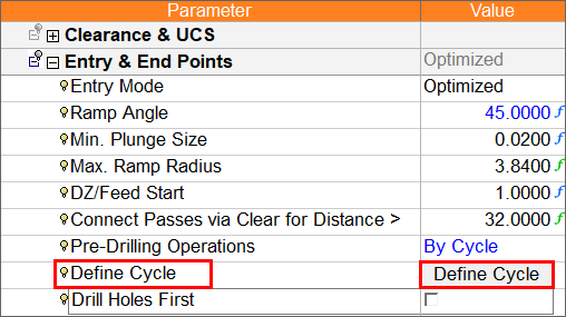
Define Cycle
Define up to three (3) drilling cycles for Rough Spiral, Rough Parallel, or Volume Pocket procedures. This option is only available if the Pre-Drilling Operations > By Cycle option is selected from the Entry & End Points Parameter table.
Defining a cycle
-
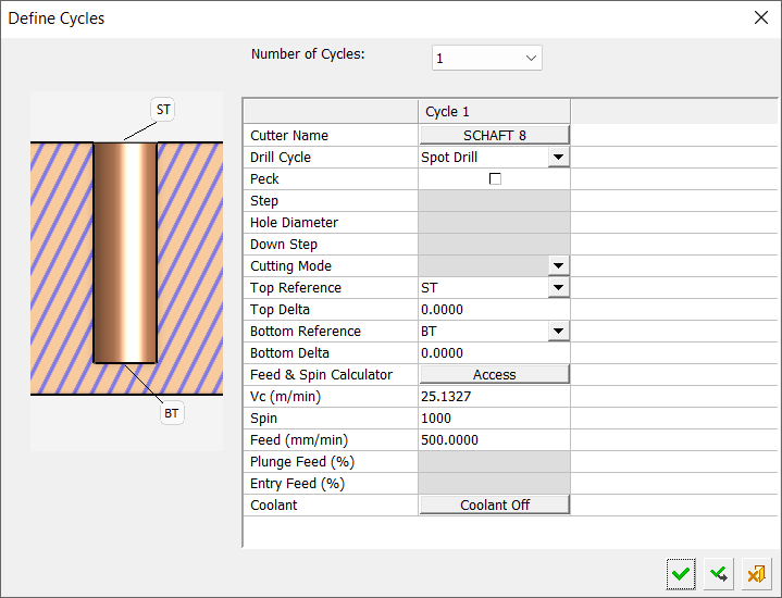
Select the Define Cycle button to open the Define Cycles dialog.
-
Select and enter appropriate criteria to define a drilling cycle(s). Refer to the Parameters table below for more information on the Define Cycles dialog parameters.
Parameters
|
Bottom Delta |
Enter the value to shift drilling below the reference points (refer to the definitions for Top Reference and Bottom Reference below). |
||||||||||||
|
Bottom Reference |
Reference point that defines where to finish the drilling operation. |
||||||||||||
|
Coolant |
Define the coolant type to be used in the drilling cycle. The available options are listed below (standard options); however, the Coolant pulldown list may also display up to six (6) additional user-defined coolant types that have been previously defined in NC Preferences
|
||||||||||||
|
Cutter Name |
Select a cutter from the Cutters and Holders table. |
||||||||||||
|
Cutting Mode |
Select a cutting mode. The options are Climb or Conventional. This option is only available if the Drill Cycle parameter is set to Profile or Helical Profile. |
||||||||||||
|
Down Step |
See Down Step. |
||||||||||||
|
Drill Cycle |
Select a drill cycle. The available options are: |
||||||||||||
|
Entry Feed (%) |
See Entry Feed. This option is only available if the Drill Cycle parameter is set to Profile or Helical Profile. |
||||||||||||
|
Feed (mm/min) |
See Feed. |
||||||||||||
|
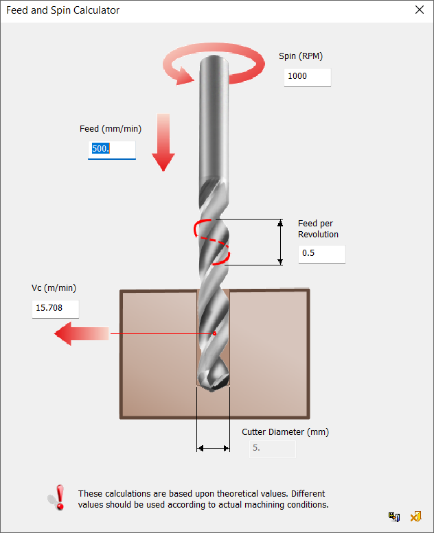
Feed & Spin Calculator |
See Feed & Spin Calculator. Click the Access button to display the Feed & Spin Calculator dialog.
|
||||||||||||
|
Hole Diameter |
Define the hole diameter. This option is only available if the Drill Cycle parameter is set to Profile or Helical Profile. |
||||||||||||
|
Number of Cycles |
Select the number of drilling cycles to be defined. The options or 1, 2, or 3. |
||||||||||||
|
Peck |
Checkbox to indicate the use of pecking in the drill cycle. When this checkbox is ON (selected), a pecking operation is performed during drilling. When this checkbox is OFF (unselected), pecking is not performed. |
||||||||||||
|
Plunge Feed (%) |
See Plunge Feed. This option is only available if the Drill Cycle parameter is set to Profile or Helical Profile. |
||||||||||||
|
Spin |
See Spin. |
||||||||||||
|
Step |
Enter a value for the peck step. This parameter is only available if the Peck checkbox is ON (selected). |
||||||||||||
|
Top Delta |
Enter the value to shift drilling above the reference points (see Top Reference below). |
||||||||||||
|
Top Reference |
Reference point that defines where to start the drilling operation. The options are:
|
||||||||||||
|
Vc (m/min) |
See Vc. |
See also:
Drill Holes First
|