|
|
Pipe  : Options and Results


Access: Open this function from the following location:
-
Select Solid > Creation > Pipe from the menu bar.
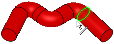
Drive a circle along a curve to add or remove material.
Create a new solid object, add to an existing solid object or remove material from a solid object by creating a solid or shelled pipe.
The following main options are available:
|
New |
Create a new solid object by creating a solid or shelled pipe. |
|
Add |
Add to an existing solid object by creating a solid or shelled pipe. |
|
Remove |
Remove material from a solid object by creating a solid or shelled pipe. |
Important: Objects created by New will be considered independent objects. Those created by Add will be added to the active object. For Remove operations, material will be removed only from the current active object.
Note: If only one object exists in the file it is automatically active, unless manually deactivated or if the active object is deleted. See Activate / Deactivate and Activating Objects.
Required Step 1  :
:
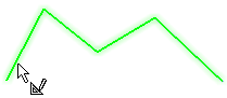
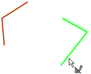
Pick one or more contours and/or curves or edges and then <exit><exit>.
|
Single selection for New: |
Multi selection for New: |
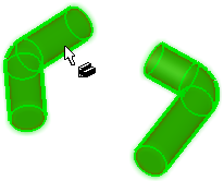
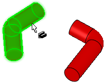
Single selection for Add/Remove: |
|
|
|
|
|
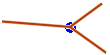
Note: Geometry with an intersection point cannot be used. If such a geometry is selected, a message is displayed and the intersection point is highlighted.
Example:Example:
Required Step 2  :
:
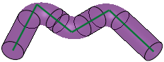
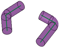
Set the pipe parameters. The pipe shape is immediately previewed according to the displayed parameters.
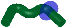
| Pipe > New - single input parameters, preview, result: | Pipe > Add - single input parameters, preview, result: | ||
|
|
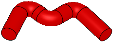
Preview: Result: |
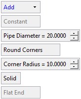
|
Preview: Result: |
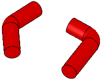
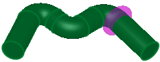
| Pipe > New - multi input parameters, preview, result: | Pipe > Remove - single input parameters and preview: | ||
|
|
Preview: Result: |
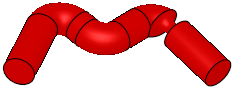
|
Preview: Result: |
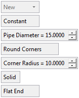

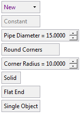
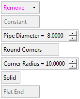
The following parameters are displayed:
|
New |
This is a dropdown list of the following options:
The default displayed option is determined as follows: New, if there is no object. Add, if there is an object and the last used option was New or Add. Remove, if there is an object and the last used option was Remove.
|
||||||||||||||||||||
|
Constant |
This is a toggle option Constant / Variable enabling you to define either a constant or variable diameter for the pipe.
If multiple loops are selected, Constant is the only option available and appears grayed out. |
||||||||||||||||||||
|
Sharp Corners |
This is a toggle option Sharp Corners / Round Corners enabling you to define either sharp or round corners for the pipe.
|
||||||||||||||||||||
|
Solid |
This is a toggle option Solid / Shelled enabling you to define either a solid or shelled body for the pipe.
|
||||||||||||||||||||
|
Flat End |
This is a toggle option Flat End / Revolved End enabling you to select the type of ending for the pipe.
If only multiple closed loops are selected in Step 1, Flat End is the only option available and appears grayed out. |
||||||||||||||||||||
|
Single Object |
This is a toggle option Single Object / Multi Objects enabling you to create single or multiple objects from the multiple entities selected in Step 1.
This option is displayed in the New option and only if multiple loops were selected in Step 1. |
||||||||||||||||||||
|
Invert Active Object |
Use the Invert Active Object option as required. This parameter is available only for open objects and deals with issues of object direction. The parameter is only available for Add and Remove operations. |

Optional Step 1 
Change the active object. This option is only available in the following cases:
-
for Add and Remove operations when creating a feature. The option is not available when editing a created feature.
-
if there is more than 1 object in the active part.
A toggle parameter is displayed; Keep Original Active Object / Activate Selected Object.
|
Keep Original Active Object |
Keep the active object originally used in the function. |
|
Activate Selected Object |
Change the active object to the selected object. Pick an object as required. |
When you have completed the steps, click OK ![]() or Apply
or Apply ![]() in the Feature Guide to complete the function.
in the Feature Guide to complete the function.
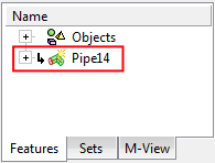
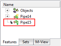
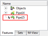
When completed, the Pipe feature will appear in the Feature Tree as follows:
|
Pipe > New: |
Pipe > Add: |
Pipe > Remove: |
|
|
|
|

|