|
|
Quick Geometry Filter
Access: Open this group of functions from one of the following locations:
-
Select the required function from the Quick Geometry Filter list in the Filters Floating toolbar.
-
Select Edit > Filter from the menu bar. Select the required function.
Define the options to quickly filter entities by geometry. Use the Quick Geometry Filter icons (in the Floating Filters Toolbar) as a short cut for the Selection Filter options.
The commands that are available in the Floating toolbar depend on the currently active file type (Part, Assembly, Drafting, or NC Manufacturing).
Note: The geometry filter functions appear in the following locations in the Cimatron window (the Quick Geometry Filter functions appear in the Filters Toolbar):
-
-
Edit > Filter menu section
-
Selection Filter dialog
-
Using the Quick Geometry Filter
Highlighted icons indicate that the specific option is ON; for example:
|
|
Option = ON |
|
|
Option = OFF |
The Filters toolbar icons (for geometry selection) are toggle options: ON/OFF.
Clicking a filter icon switches ON that specific filter functionality. Multiple filters may be selected.
Double-clicking a filter icon switches it ON and switches OFF all other filters. To return to the default filter state, click the Reset Selection Filters button:
![]()
Quick Geometry Filter options
The following functions are available in the Filters Toolbar (the toolbar for the assembly environment is displayed below):
![]()
The filters are described below in their order of appearance.
|
|
Reset the selection filter to its default settings only for the current function, stage, and option. To reset all filters of all tools to the system defaults, use the Reset Filter Default Preference option. |
|||||||||||||||||||||
|
|
The Selection Filter enables you to define the types and attributes of geometry available for selection. For example, if only Faces are marked in the Selection Filter, then only Faces will be available for selection in the graphics window for the current operation. |
|||||||||||||||||||||
|
|
Open the UCS Manager dialog to select, hide, and show UCSs. |
|||||||||||||||||||||
|
|
Enable/Disable the selection
of objects. |
|||||||||||||||||||||
|
|
Enable/Disable the selection of faces. |
|||||||||||||||||||||
|
|
Enable/Disable the selection of sketches, composites and single curve wires. Note: To distinguish between a single curve within a composite curve and a standalone curve, unselect the Single Curve Wire box in the Selection Filter dialog (by default this is selected). |
|||||||||||||||||||||
|
|
Enable/Disable the selection of edges and curves. |
|||||||||||||||||||||
|
|
Enable/Disable the selection of threads. |
|||||||||||||||||||||
|
|
||||||||||||||||||||||
|
|
Enable/Disable the selection of symbols (PMI). |
|||||||||||||||||||||
|
|
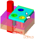
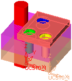
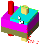
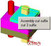
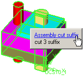
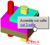
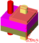
Enable/Disable the selection of cutting objects. This filter is available in the Assembly environment when the Hide/Show Entities/Components icon ( Notes:
|
|||||||||||||||||||||
|
|
Enable/Disable the select of assembly components and sub-assemblies. The interaction differs when picking components in an assembly or in a sub-assembly.
|
|||||||||||||||||||||
|
|
Enable/Disable the selection of segments (of curves). This icon is displayed when a Drafting file is open. |
|||||||||||||||||||||
|
|
Enable/Disable the selection of groups. This icon is displayed when a Drafting file is open. |
|||||||||||||||||||||
|
|
Enable/Disable the selection of views. This icon is displayed when a Drafting file is open. |
|||||||||||||||||||||
|
|
Enable/Disable the selection of NC toolpaths (tool motions displayed in the graphic window). This icon is displayed when an NC file is open. |
|||||||||||||||||||||
|
|
Enable/Disable the selection of NC stock objects. This icon is displayed when an NC file is open. Note: Stock objects exist only in Machining Simulation. |
|||||||||||||||||||||
|
|
Enable/Disable the selection of points. The point selection flyout is displayed in the Filters Floating Toolbar. |
|

