|
|
Rib  : Options and Results
![]()
![]()

Access: Open this function from the following location:
-
Select Solid > Creation > Rib from the menu bar.
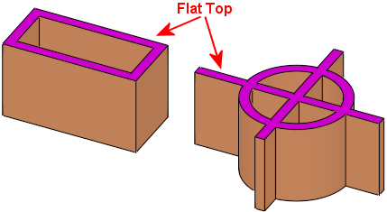
Create a rib to strengthen regions of the part. The rib is based on a 2D wireframe with a defined thickness, draft angle, direction, and a flat or rounded top.
Required Step 1 
-
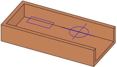
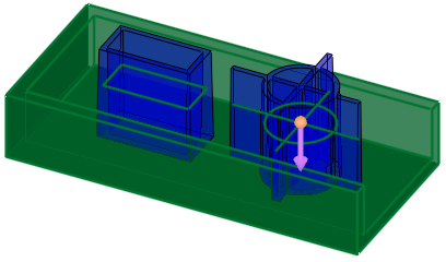
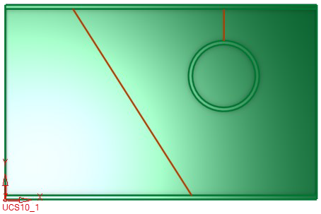
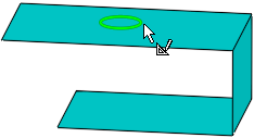
Pick the rib centerline curves from which the rib is to be created.
Note: You can select multiple rib curves as required for your work results.
-
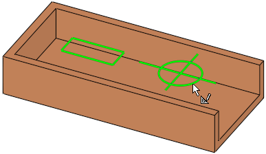
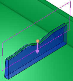
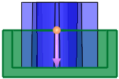
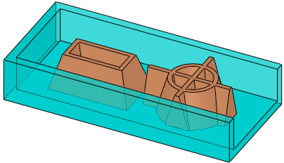
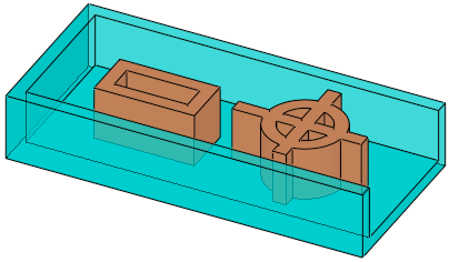
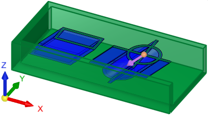
The rib will be created on both sides of the selected reference geometry. In the image below, the DARK GREEN contours represent the selected reference geometry.
A smooth 3D contour or a 2D contour may be picked, where the direction of the latter is also parallel to the 2D contour plane.
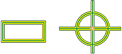
ExamplesExamples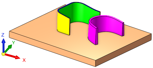
3D reference contour examples
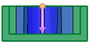
2D reference contour example, where the direction (Step 2 of the function) is parallel to the 2D contour plane
-
ExitExit to proceed to Step 2.
Required Step 2 
-
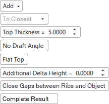
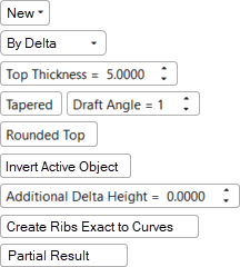
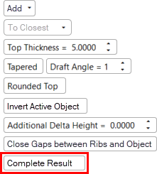
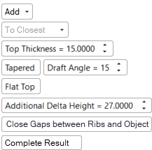
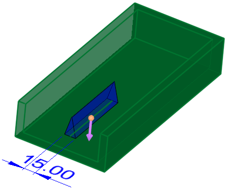
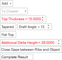
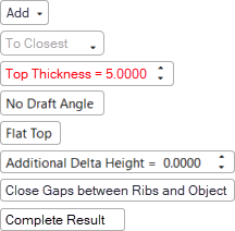
Set the parameters and define the rib direction. The image below shows the screen parameters that are displayed for the Rib function.
Note: See the Parameters table below for more information on the available Rib parameters and how they can be used to produce the desired work results.
|
|
|
|
|
|
Note that the Invert Active Object parameter is only displayed for open objects and deals with issues of object direction. Cimatron automatically displays this parameter if open objects are detected. See the Parameters table below for more information on the this and other parameters. |
|||
-
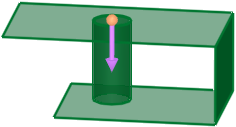
To define the rib direction, a direction arrow is displayed. The rib direction can be parallel or normal to the plane of the picked contour or less than 45° from the normal direction. See the Top Thickness parameter defintion for possible effects of the rib direction.
Optional Step 1 
-
Change the active object.
A toggle parameter is displayed, Keep Original Active Object / Activate Selected Object. Select the appropriate option as required for your work results.
|
Keep Original Active Object |
Keep the active object originally used in the function. |
|
Activate Selected Object |
Change the active object to the selected object. Pick an object as required. |
-
When you have completed the steps, click OK
 or Apply
  in the Feature Guide to complete the function.
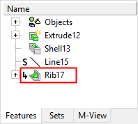
When completed, the Rib feature will appear in the Feature Tree.
Using the Conflict Solver to successfully apply a Rib
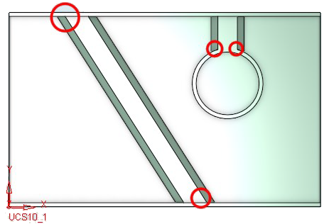
There may be instances where the Rib function fails to produce the desired result due to geometric limitations involving extrudes, tapers, rounds, or other features that comprise a rib. In these cases, the Conflict Solver will automatically open, providing you with helpful information to achieve the correct results, such as recommending that some rib curves be unselected for example.
For more information on the Conflict Solver and its use with the Rib function, see the Complete Result / Partial Result parameter definition in the Parameters table below.
|
|
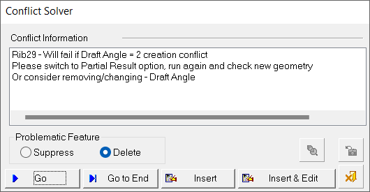
The Conflict Solver dialog displays a warning that the Rib function will fail as it is currently defined. The Conflict Information area also lists recommendations for successfully generating the rib. In this example, Conflict Solver recommends:
See Conflict Solver for more information. |
Note: The Conflict Solver will appear whenever there is a rib curve failure, regardless if the Complete Result or Partial Result option is selected from the Rib parameters.
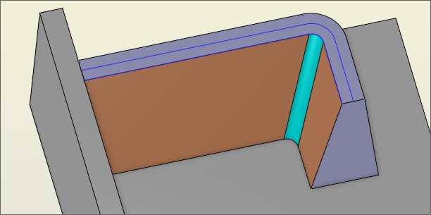
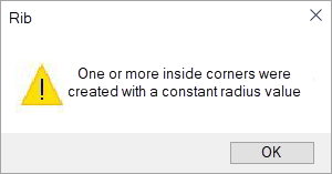
Ribs with draft angles
A rib with a small inside corner can be created with no taper; however, when applying a draft angle, Cimatron may have issues creating the rib due to difficulty analyzing the geometry. In this case, Cimatron creates one or more inside corners with a constant radius value.
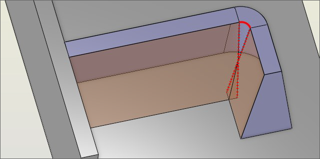
Cimatron displays the partial results as well as a warning message. Click OK and modify the rib curve as necessary or modify the draft angle options.
|
|
|
Parameters
|
Add / |
This toggle option allows you to add a rib as a new solid object or add it to an existing solid object.
|
||||||||||||||
|
Additional Delta Height |
Use this parameter to increase or decrease the rib's delta height. A positive value increases the rib's height and a negative value decreases it. The default value is 0. Note: Positive and negative values are permitted with this parameter.
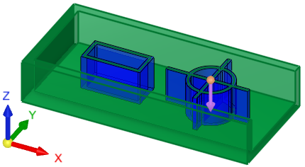
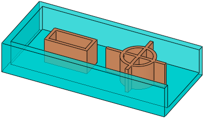
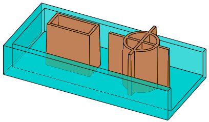
In the examples below, Additional Delta Height (with a value of 30) is applied to the ribbed parts on the right, which have been moved opposite of the direction arrow.
When this option is used with a Tapered draft angle, the Top Thickness value is measured at the plane of the reference contour selected in Step 1. In the example below, the rib thickness at the reference contour plane is defined as 15. If the resultant thickness of the top of the rib is zero or less (as a result of a change in the parameter values of either the Top Thickness, Tapered (Draft Angle), or Additional Delta Height), the Top Thickness and Additional Delta Height values are displayed in RED and the function does not execute.
|
||||||||||||||
|
By Delta / |
The toggle options enabled for this parameter depend on the option selected for the Add / New parameter listed above.
|
||||||||||||||
|
Close Gaps between Ribs and Object / |
This toggle option allows you to select the method for closing gaps between ribs and faces.
|
||||||||||||||
|
This toggle option instructs the system to generate a complete or partial result for the rib creation.
|
|||||||||||||||
|
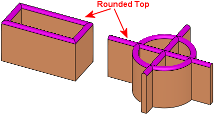
Flat Top / |
This toggle option allows you to create ribs with flat or rounded tops.
|
||||||||||||||
|
Invert Active Object |
This parameter is only displayed for open objects and deals with issues of object direction.
|
||||||||||||||
|
No Draft Angle / |
This toggle option allows you to create straight or tapered rib walls.
|
||||||||||||||
|
Use this parameter to set the thickness of the created rib. Default = 5 mm or 0.2 inches
If the rib direction is not exactly normal to the plane of the picked contour (with an angle up to 45° from the normal), the top thickness may not be uniform. To highlight this possibility, the Top Thickness parameter and value are displayed in RED.
|


|