|
|
Taper  : Options and Results
Access: Open this function from one of the following locations:
-
Click the
 button
in the toolbar.
 -
Select Solid > Main Tools > Taper from the menu bar.
Taper faces.
This function tapers selected faces that have a common edge with, or are intersected by, either a selected neutral contour or a neutral plane. If the contour/plane intersects the faces, the faces can be tapered on one side or both sides of the intersection.
Notes:
-
When creating a taper, the Automatic Preview operation may be time-consuming. A checkbox in the Preferences enables you enable/disable the Automatic Preview option in the Feature Guide when executing the Taper function.
-
The default color of the taper faces is defined in the Preferences.
Required Step 1 
If the Taper is to be created from a neutral contour; pick a contour or a series of edges. If the Taper is to be created from a neutral plane; pick a plane or planar face.
|
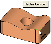
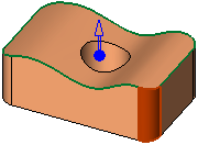
Neutral Contour: Note: If you select an edge that is smoothly connected to adjacent edges, all smooth edges will be automatically selected. |
Neutral Plane: |
||
|
Select one edge... |
...all smoothly connected edges are automatically selected. |
In the example below, the bottom face is selected: |
|
|
|
|
|
|
The Neutral Plane options are:
|
Keep Size at Plane Level |
When tapering, keep the original size of the entities at the level of the neutral plane (where the selected plane intersects the entities to be tapered).
|
||||||||||||
|
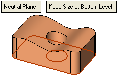
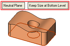
Keep Size at Bottom Level |
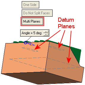
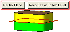
When tapering, keep the original size of the entities at the bottom level. The bottom level is identified by one or more temporary datum planes (single or multiple) that are displayed parallel to the selected neutral plane. The temporary planes are displayed in the opposite direction of the taper direction arrow, and at the farthest location of the faces selected to be tapered. The taper direction arrow is selected in step 2. The temporary datum planes are displayed in step 3.
|
If the Neutral Contour option is used, press <exit><exit> when all curves/edges or plane/planar face are selected, to jump to the second step.
If the Neutral Plane option is used, once the plane or planar face is selected, the system automatically jumps to the second step of the function.
Required Step 2 
Pick the faces to be tapered and define the taper direction. The following options are displayed in this step:
|
If Neutral Contour was selected in step 1: |
If Neutral Plane was selected in step 1: |
|
|
|
The taper direction is defined either by using the directional arrow ( ) or by using the flip arrow (
 ). For both arrows, the directions can be flipped by clicking the arrowhead.
The flip arrow is displayed if the Neutral Contour option was used in step 1 and the Normal to Plane Direction option is used in step 2. The directional arrow is displayed for the other options.
Notes:
-
If the Neutral Contour option was selected in step 1:
-
-
Each face selected in step 2 must have a common edge with the selected contour. Initially, you will be able to select a face that does not have a common edge with the contour, however, in Required Step 3, where you define the taper angle and direction, any face that does not have a common edge with the selected contour, will be removed from the selection (it will not participate in the taper operation).
-
The default taper angle depends on the type of curves/edges selected in step 1:
-
-
If 2D curves/edges were selected, the default taper direction is normal to the curve plane.
-
If 3D curves/edges were selected, the default taper direction is parallel to the smallest side of the curve bounding box. You can use the arrow to change the taper direction.
-
-
-
If the Neutral Plane option was selected in step 1, an additional toggle option is displayed in step 2 that enables you to define the taper direction.
|
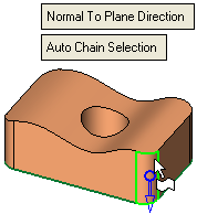
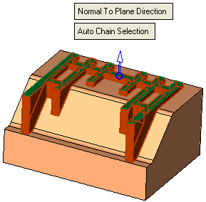
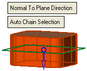
Normal to Plane Direction |
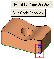
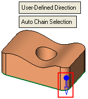
This is a toggle option (Normal to Plane Direction / User-Defined Direction) that enables you to define the taper direction. This toggle option is only displayed if the option Neutral Plane is selected in step 1. The toggle options are as follows:
|
||||||||
|
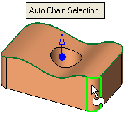
Auto Chain Selection |
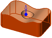
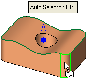
This is a toggle option (Auto Chain Selection / Auto Selection Off) that enables you to choose how the faces to be tapered are selected. The toggle options are as follows:
|
Press <exit><exit> when all faces are selected.
When switching to step 3, the system checks if the selected faces are intersected by (or have a common edge with) the neutral plane or contour:
-
If the options Neutral Plane and Keep Size at Plane Level were selected in step 1 and User-Defined Direction was selected in step 2; when switching to step 3, the system checks if the selected faces are intersected by (or have a common edge with) the neutral plane.
-
If the option Neutral Contour was selected in step 1; when switching to step 3, the system checks if the selected faces have a common edge with the wire/edges of the neutral contour or if they can be split by the wire (with a tolerance of 0.5 mm).
-
In both the above cases:
-
-
If none of the selected faces meet the criteria, an appropriate message is displayed, the faces remain unselected and you cannot switch to step 3.
-
If some of the selected faces meet the criteria, an appropriate message is displayed, the system switches to step 3, but those faces that do not meet the criteria are unselected.
-
If all of the selected faces meet the criteria, the system switches to step 3 with all the selected faces.
-
Required Step 3 
Set the taper angle and direction. The following options are displayed in this step:
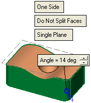
The interaction in this step depends on whether a neutral contour or plane was selected in step 1, and whether the contour/plane intersects the faces selected to be tapered in step 2. If the contour/plane intersects the faces, the faces can be tapered on one side or both sides of the intersection. If the neutral plane intersects faces, the faces can also be split and then tapered.
|
One Side |
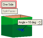
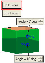
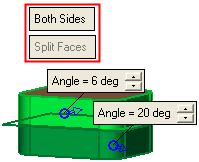
This is a toggle option (One Side / Both Sides) that enables you to taper either on one side or both sides of a neutral contour/plane that intersects the faces to be tapered. This option is only available if the neutral contour/plane intersects the faces to be tapered; in all other cases the option is grayed out. The toggle options are as follows:
|
||||||||||||
|
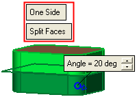
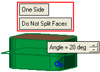
Split Faces |
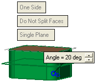
If there is at least one face that is intersected (can be split) by the neutral plane, or if some faces are above the plane and others below (the faces are not necessarily intersected by the plane - as in the example below, yellow faces above the plane and green faces below), this toggle option (Split Faces / Do Not Split Faces) enables you to define whether or not the faces are split at the intersection level. This toggle option is only available if the following options are selected: Neutral Plane and Keep Size at Plane Level (step 1), Normal to Plane Direction (step 2) and One Face (step 3); for all other neutral plane options, this toggle option is displayed at the appropriate setting, but grayed out.
The toggle options are as follows:
|
||||||||||||
|
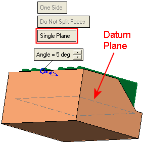
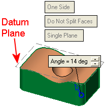
Single Plane |
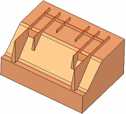
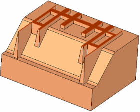
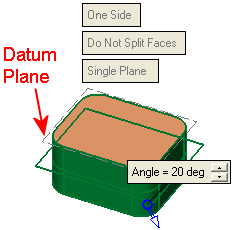
This is a toggle option (Single Plane / Multi Planes) that enables you to define if a single or if multiple "bottom level" temporary plane(s) are used as a reference start position for the taper operation. The "bottom level" is identified by temporary datum plane(s) (single or multiple) that are displayed parallel to the selected neutral plane. The temporary plane(s) are displayed in the opposite direction of the taper direction arrow, and at the farthest location of the faces selected to be tapered. In this example, the green faces are the neutral plane and the red faces are selected to be tapered.
The differing taper results of the single/multi plane options, are shown in the parameter explanations below. This toggle option is only available if the following options are selected: Neutral Plane and Keep Size at Bottom Level (step 1). The toggle options are as follows:
|
||||||||||||
|
Angle |
The taper angle is the number of degrees between the face normal and the draft direction, regardless of the angle of the face before the taper was assigned (the absolute value). The angle direction is defined by flipping the displayed arrow ( |
The following interaction possibilities are available:
- Neutral Contour - No IntersectionNeutral Contour - No Intersection
The neutral contour does not intersect the selected faces if the faces are on one side of the contour.
ExampleExample: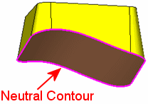
In this case, the interaction is as follows:
Neutral Contour - no intersection:
Selected faces are on one side of the contour.Interaction:
Set the taper angle and direction for the single set of faces.Result:
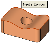
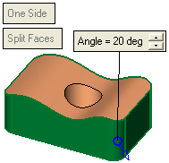
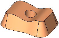
- Neutral Contour - IntersectionNeutral Contour - Intersection
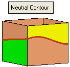
The neutral contour intersects the selected faces if the faces are on both sides of the contour.
ExamplesExamples: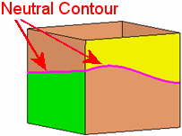
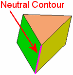
In this case, the interaction is as follows:
Neutral Contour - intersection:
Selected faces are on both sides of the contour:Interaction:
The faces are split at the intersection.
Set the taper angle and direction for the faces on either one side or on both sides of the neutral contour.Result:



- Neutral Plane - No IntersectionNeutral Plane - No Intersection
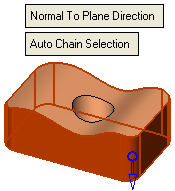
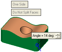
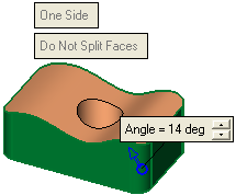
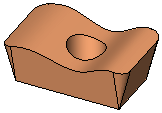
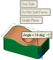
The neutral plane does not intersect the selected faces if the faces are on one side of the plane. In this case, the interaction is as follows:
Step 1:
Neutral Plane - no intersection:
Selected faces are on one side of the plane:Step 2:
Set the taper direction.Step 3:
Set the taper angle and direction for the single set of faces.
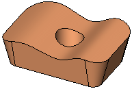
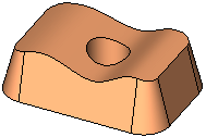
One Side/Both Sides toggle is grayed out.Result:
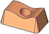
Whatever the taper direction and angle, the size of the original entities, at the appropriate plane level, remains the same.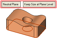

- Neutral Plane - IntersectionNeutral Plane - Intersection
The neutral plane intersects the selected faces if the faces are on both sides of the plane.
ExamplesExamples: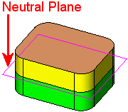

In this case, the interaction depends on whether one or both sets of faces are to be tapered. The One Side/Both Side toggle option is displayed.
Step 1:
Neutral Plane - intersection:
Selected faces are on both sides of the plane:Step 2:
Set the taper direction.Step 3:
Set the taper angle and direction.Result:
Whatever the taper direction and angle, the size of the original entities, at the appropriate plane level, remains the same.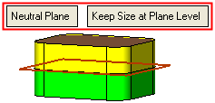





When you have set the parameters, click OK ![]() or Apply
or Apply ![]() in the Feature Guide to complete the function. The taper is applied to the faces.
in the Feature Guide to complete the function. The taper is applied to the faces.
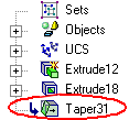
When completed, the Taper feature will appear in the Feature Tree as follows:
|


