|
|
Modeling Preferences > General

Access: Invoke this function from one of the following locations:
-
Select the Preferences button
 from the Quick Access Toolbar, or
 -
Select Tools > Main Tools > Preferences from the menu bar.
Navigate to Modeling > General.
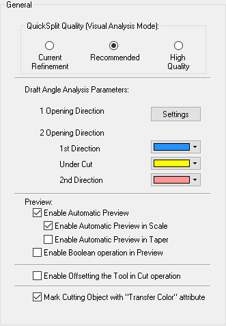
Set default parameters for QuickSplit and Draft Angle Analysis operations and also the Preview option in the Feature Guide.
The General dialog is displayed.
Interaction
Set the following default QuickSplit options:
|
Current Refinement |
Use the current refinement of the display faceting. If the refinement (Surface tolerance & maximum grid lines) is very tight, the Splitting may take some time. |
|
Recommended |
Re-facet the displayed faces (that were not already attached to any direction yet) by the default tolerance. The refinement of the display does not affect this option. |
|
High Quality |
Re-facet the displayed faces (that were not already attached to any direction yet) by the tight tolerance. The refinement of the display does not affect this option. |
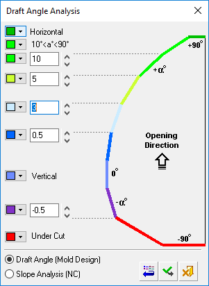
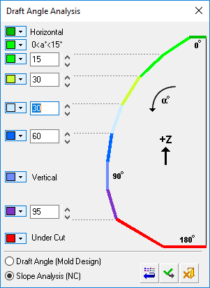
Set the default Draft Angle Analysis and Direction Analysis parameters. Press the Settings button to display the Draft Angle Analysis dialog.
Note: In the Preferences, the Restore Defaults button does not appear in the Draft Angle Analysis dialog.
|
1 Opening Direction |
Analyze the part from one direction. This option divides the part into multiple colors, depending on the draft angles. Set the default draft angle settings (colors and their values) to be used when this option is selected in analysis functions. Click the Settings button to display the Draft Angle Analysis dialog, to set the parameters.
|
||||
|
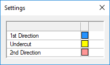
2 Opening Directions |
Analyze the part from two pull directions. This finds and manages the primary opening direction and also allows you to see faces assigned to the core and cavity as well as undercuts. This option divides the part into the following color-coded sections: - 1st Direction (selected primary opening direction) - Under Cut (for lifters, sliders,etc.) - 2nd Direction (opposite opening direction - for core or cavity) Vertical faces are assigned to one of the 2 directions, as defined in the Direction Analysis parameters. Set the default colors to be used when this option is selected in analysis functions. These colors appear in the Settings dialog when this option is selected.
|
Set the appropriate Preview options for use in the Feature Guide when executing a function:
|
Enable Automatic Preview |
Enable the Auto Preview option in the Feature Guide when executing a function. This enables you to immediately see a preview of the results of an operation before executing a function. If the Enable Automatic Preview option is ON, additional options becomes available. |
||
|
Enable Automatic Preview in Scale |
Set Automatic Preview ON or OFF for Scale and Shrinkage Compensation operations. Note: Non-Uniform operations for Scale and Shrinkage Compensation functions will only work in manual preview mode for performance issues, regardless of the defined preference options or if automatic preview is set in the Feature Guide. See Non-Uniform Scale / Shrinkage Compensation. By default, this checkbox is ON. This option is grayed out if the Enable Automatic Preview checkbox is OFF. |
||
|
Enable Automatic Preview in Taper |
Set Automatic Preview ON or OFF for Taper operations. By default, this checkbox is OFF. This option is grayed out if the Enable Automatic Preview checkbox is OFF. |
||
|
Enable Boolean operation in Preview |
Enable Boolean operations when previewing the results of an operation. This enables you to immediately preview the results of a boolean operation, rather than preview the assisting feature used in the operation. When this checkbox is marked
|
Enable Offsetting the Tool in Cut operation: When this checkbox is marked  , this enables you to offset the cutting object in a cut operation. When ON, this displays the toggle option Don't Offset / Offset Cutting Object in cut operations.
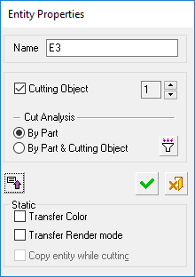
Mark Cutting Object with "Transfer Color" Attribute:
When marking an object as a Cutting Object (usually used for catalog parts), the Transfer Color attribute option in the cutting object attributes function (Attach Name to Entity) enables the color of the cutting object to be transferred to the cut part when the cut is performed. This may be required for color coding of holes, for example. The Transfer Color option can also be controlled from this Preference option.
When this checkbox is marked , and when creating a cutting object by using the Cutting Object function, this also turns ON the Transfer Colors option in the cutting object attributes function (Attach Name to Entity).
Example dialog in the Attach Name to Entity function.Example dialog in the Attach Name to Entity function.
|
|
The dialog from the Attach Name to Entity function showing the Transfer Color attribute checkbox. This checkbox is influenced by the above Preference setting when using the Cutting Object function. |
Press the appropriate approval option.
|