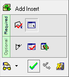
Add Insert 


Access: Open this function from one of the following locations:
-
Select Mold Design > Insert > Add Insert from the menu bar.
-
Select Die Design > Insert Tools > Add Insert from the menu bar.
-
Select Insert > Add Insert from the Mold Design Guide or Die Tool Design Guide (DieDesign).
Create the insert geometry and its cutting object including reliefs and cut the plate with it.
See Insert Tools for an introduction to inserts.
The Add Insert function enables full automation over the entire insert design process, resulting in a much quicker and easier experience for the user. It enables the creation of the insert even before the plate has been cut and allows it to be sent for machining at this early stage.
The automatic functionality includes the standard aspects of insert creation, such as design of the insert shape and automatic cutting of the components or plate it goes through.
It also facilitates additional aspects of the process:
- Creation of the insert parts using a sketch:
- The sketch that is used to create the insert part – regardless of where it is located in the project – together with all dimensions, are moved to the new insert part file. This simplifies the editing process for the user.
- In addition to the traditional cut, the tool offers the ability to automatically add reliefs and manage all of its dimensions.
- The tool shows whether the cutting object is correctly designed or if it incorrectly interferes with the object’s geometry.
- Creation of the insert parts by selecting faces.
- Automatic creation of a cutting object, including Cut Manager.
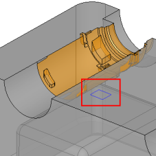
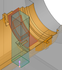
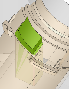
Example showing added inserts:
|
A sketch for designing the insert is created. |
The insert is created, extruded and then cut by the active faces. |
The Result: An insert part is created along with all the corresponding cuts. In addition, a new insert part file is created and the sketch used to create the insert is moved to this file (becomes a reference feature of the new insert part file). |
|
|
|
|
General Interaction
The following is the Feature Guide for Add Insert.
|
|
|
Required Step 1 ![]() : Pick a closed 2D sketch, wire or reference faces and define other parameters.
: Pick a closed 2D sketch, wire or reference faces and define other parameters.
Required Step 2 ![]() : Pick the options to define the top skin of the insert.
: Pick the options to define the top skin of the insert.
Optional Step 1 ![]() : Define a draft angle.
: Define a draft angle.
Optional Step 2 ![]() : Define the cutting object parameters for the insert.
: Define the cutting object parameters for the insert.
Optional Step 3 ![]() : Using the Cut Manager, mark/unmark the checkboxes for parts to be cut.
: Using the Cut Manager, mark/unmark the checkboxes for parts to be cut.
Detailed Interaction
See Options and Results.