|
|
Add Insert  : Options and Results


Access: Open this function from one of the following locations:
-
Select Mold Design > Insert > Add Insert from the menu bar.
-
Select Die Design > Insert Tools > Add Insert from the menu bar.
-
Select Insert > Add Insert from the Mold Design Guide or Die Tool Design Guide (DieDesign).
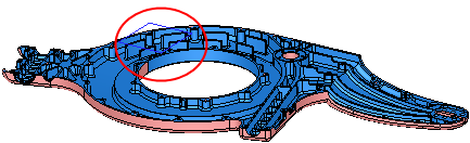
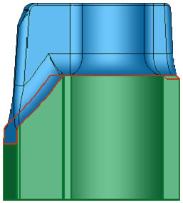
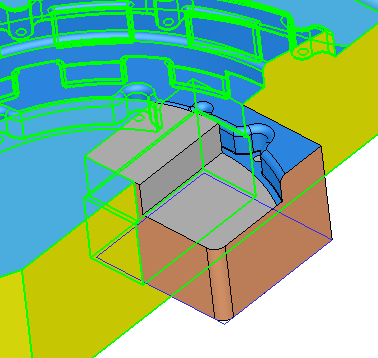
Create the insert geometry and its cutting object including reliefs and cut the plate with it.
The Add Insert function enables full automation over the entire insert design process, resulting in a much quicker and easier experience for the user. It enables the creation of the insert even before the plate has been cut and allows it to be sent for machining at this early stage.
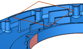
The automatic functionality includes the standard aspects of insert creation, such as design of the insert shape and automatic cutting of the components or plate it goes through.
|
|
|
Required Step 1 
- Pick a closed 2D sketch, wire or reference faces and define other parameters.
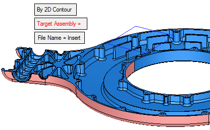
By 2D Contour
This is a toggle option By 2D Contour / By Reference Faces that enables you to choose how to define the insert.
By 2D Contour
Pick a closed 2D sketch or wire.
By Reference Faces
Pick one or more reference faces that belong to the same body.
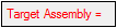
Target Assembly
The Target Assembly field displays the name of the selected assembly. The parameter is displayed in red when it is empty (before a part is picked or if you clear the selection). After a part has been picked, the parameter is grayed out and displays the name of the selected assembly. For example:
Before picking the target assembly.
After picking the target assembly.
The default target assembly is the assembly to which the active part belongs (when invoking the function). When the active file is an assembly file (not the main assembly), this will be the default assembly.
Note: For the Target Assembly the parameter:
-
If the system selected the assembly automatically (the default assembly), the text appears in purple.
-
If the assembly was manually selected, the text appears in black.
-
If no assembly is selected, the text appears in red.
File Name
The sketch that is used to create the insert part, regardless of where it is located in the project, together with all dimensions, is moved to a new insert part file. This simplifies the editing process for the user. See the example below (for Keep Original Sketcher/Wire).
Set the file name as required. The default file name is Insert; if such a part is already exists in the picked assembly, the default name is Insert#1, etc.
Delete Original Sketcher/Wire This is a toggle option Delete Original Sketcher/Wire / Keep Original Sketcher/Wire that appears only if the option 2D Contour is used, and enables you to
Delete Original Sketcher/Wire
Delete the sketch or wire used to define the insert.
Keep Original Sketcher/Wire
Keep the sketch or wire used to define the insert and move it to the new file (defined in File Name, above). The sketch is moved with all the defined dimensions and relations.
If a reference of the work part (or any other part involved in the cut operation) is used in the sketcher, this reference remains in the moved sketch.
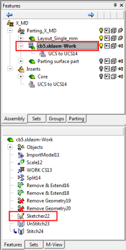
See the example below.Before invoking the Add Insert function. Note that the sketch is in the work part.
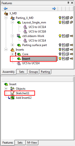
After execution (when the Keep Original Sketcher/Wire option is used), note that the sketch has been moved (from the work part) to the new insert part.
-
- Click OKOK
 when complete to continue..
Required Step 2 
-
Pick the options to define the top skin of the insert.
The parameters displayed depend on the option selected in Required Step 1:By 2D Contour parameters
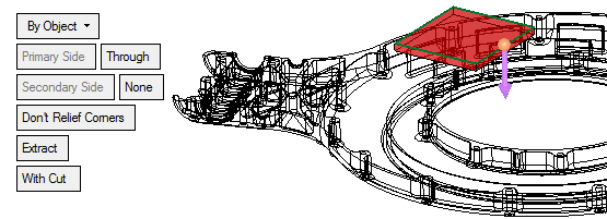
By Object
This is a dropdown list of the following options:
By Parting Assembly
The insert is cut by the closest parting split direction in the extrude direction of the insert. (Only split faces within the boundaries of the projected sketch are selected).
In this option there is no selection, the analysis (for the cutting skin of the extrude object) is done automatically.
Notes:
-
The parting surfaces must be created in the Parting Surface Part.
-
If a parting assembly does not exist in the assembly, this option is not displayed.
By Selected Faces
The insert is cut by the selected faces within the boundaries of the projected sketch.
In this option you can pick one or more faces or a single plane from different parts in the assembly.
By Object
The insert is cut by the farthest faces of the body within the boundaries of the selected faces. This is the default option.
The result depends on the additional parameter selected, either Extend or Extract - see below.
In this option you can pick a single object; if you pick another object, it will become selected and previous one will be cleared.
Primary Side
Set the primary parameters for the extrude operation on the entity selected in Step 1 (in the direction of the direction arrow).
The By Delta / Through toggle option is displayed; if By Delta is selected, a Delta value can be defined.
Secondary Side
Set the secondary parameters for the extrude operation on the entity selected in Step 1 (from the sketcher plane to the opposite side of the direction arrow).
The By Delta / None toggle option is displayed; if By Delta is selected, a Delta value can be defined and the extrude is in both directions.
Max. Gap
This parameter is displayed only if the options By Parting Assembly or By Selected Faces are selected.
Enter the Max. Gap tolerance to join objects. This parameter controls the stitch tolerance when healing multiple objects with gaps.
The initial default tolerance value is as defined in the Preferences. See the same Preference also for the tolerance range.
Changes to the tolerance will not be reflected on the screen until the Preview button is pushed.
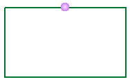
Don't Relief Corners
This is a toggle option Relief Corners / Don't Relief Corners that enables you to control outside sharp corners.
Example:Example:Don't Relief Corners
Relief Corners: Round
Relief Corners: Flat
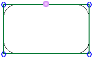
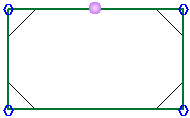
When the Relief Corners option is used, additional parameters are displayed and hexagon shaped 'handles' appear on the outside sharp corners.
Example:Example: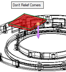
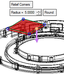
Radius
Set the global radius for all the relief corners.
To set a local radius on one or more sharp corners, pick the relevant corner hexagon; a dimension box appears at each picked hexagon, displaying the radius value. Set the value as required.
Example:Example: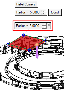
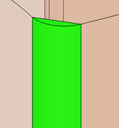
Round
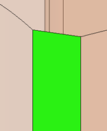
This is a toggle option Round / Flat that enables you to define the shape of the relief corner.
Example:Example:Relief Corner: Round
Relief Corner: Flat
Extract
This parameter is displayed only if the option By Object is selected. This is a toggle option Extract / Extend that enables you to define the insert result.
Extract
The insert is cut within the boundaries of the selected faces. This is the default option.
See the examples below.Extend
The insert is cut within the boundaries of the selected faces and extended to the sketch.
See the examples below.Extract:
Extend:
With Cut
This is a toggle option With Cut / Without Cut that enables you to choose whether or not to cut the relevant parts.
When using the option With Cut, the system analyzes and cuts only parts from the same sub-assembly.
By Reference Faces parameters
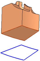
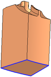
Through
This is a toggle option Through / Minimum Distance that enables you to define the length of the insert.
Through
Extend the insert to the "bottom" face of the body. The Through option is with respect to the object containing the reference faces. This is the default option.
Example:Example: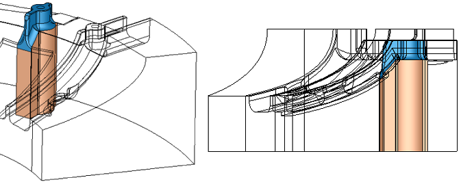
Minimum Distance
Define a minimum distance for the insert. A Minimum Distance value parameter is displayed when this option is selected.
Example:Example: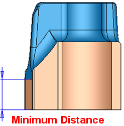
With Cut
This is a toggle option With Cut / Without Cut that enables you to choose whether or not to cut the relevant parts.
When using the option With Cut, the system analyzes and cuts only parts from the same sub-assembly.
-
-
Click OKOK
when complete to continue.
Optional Step 1 
-
Define a draft angle.
-
If the Secondary Side option in Required Step 2 was defined as By Delta and set with a positive value, two different draft angles can be defined.
-
If the By Reference Faces option was selected, only one angle can be defined.
Without a draft angle:
With a draft angle:
-
Optional Step 2
-
Define the cutting object parameters for the insert. The following parameters are displayed:
Cutting Object
This is a toggle option Cutting Object / None which enables you to define a cutting object or not. The default is Cutting Object.
If None is selected, no parameters are displayed and the systems exits the option.
Extend Active Faces By
Extend the active faces by the entered value. This option is only displayed if the By Reference Faces option is selected in Required Step 1.
Example:Example: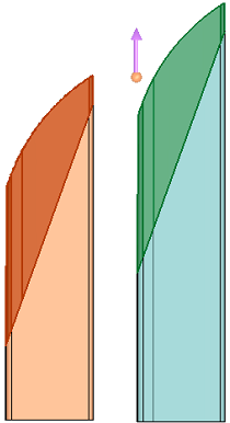
The arrow direction is defined in Required Step 2.
Note: If the extending faces include undercut faces, this option is grayed out.
Don't Relief Corners
This is a toggle option Relief Corners / Don't Relief Corners which enables you to control outside sharp corners. This option is only displayed if the By 2D Contour option is selected in Required Step 1.
When the Relief Corners option is used, additional parameters are displayed and hexagon shaped 'handles' appear on the outside sharp corners.
Example:Example:Round Corner
Round the corners. The following parameter is displayed:
Radius
A Radius parameter is displayed to set the global round radius for all the relief corners.
To set a local round radius on one or more sharp corners, pick the relevant corner hexagon; a dimension box appears at each picked hexagon, displaying the radius value. Set the value as required.
If the relief radius value defined in Required Step 2 is smaller than the relief radius value in this step, the radius parameters in both steps are displayed in red.
Drill Relief
Drill relief the corners. The following parameters are displayed:
Diameter
A Diameter parameter is displayed to set the global round diameter for all the relief corners.
To set a local diameter on one or more sharp corners, pick the relevant corner hexagon; a dimension box appears at each picked hexagon, displaying the diameter value. Set the value as required.
Move Center Point By
Set the value by which to move the center point of the drill relief.
Examples:Examples: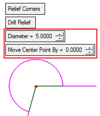
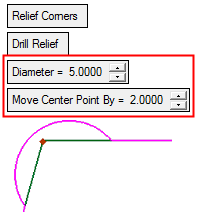
The Diameter value must be at least twice the Move Center Point value.
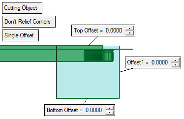
Single Offset
This is a toggle option Single Offset / Double Offset which enables you to set additional offset parameters. This option is only displayed if the By 2D Contour option is selected in Required Step 1.
Single Offset
Create a single offset. This is displayed as Offset 1.
Example:Example:See the offset parameter descriptions below.
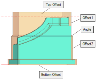
Double Offset
Create a double offset. This is displayed as Offset 2. In addition, the Angle value is also displayed.
Example:Example: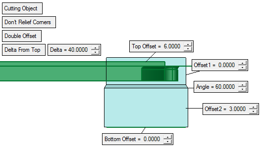
See the offset parameter descriptions below.
Offset parameter descriptions:
Top Offset The offset from the highest boundary point of the selected faces. Offset 1 The offset from the insert walls. Offset 2 If Single Offset is toggled to Double Offset, Offset 2 is displayed. This is the wall offset defined below the point set by the Delta From Top value. Angle If Double Offset is used, Angle is displayed. This is the angle is defined between the two offset walls (Offset 1 and Offset 2). Bottom Offset The offset from the lowest boundary point of the selected faces.
Optional Step 3 
- Using the Cut Manager, mark the parts to be cut.
Select the parts to be cut by defining them in the displayed Cut Manager dialog. This option enables you to manually control which parts are to be cut. - Click OKOK
 or ApplyApply
 in the Feature Guide to complete the function.
Note: After execution, only the minimum required related faces are kept in the feature to make the insert shape (even if the By Parting Assembly or the By Object option is used). When Editing the feature, the option will always be shown as By Selected Faces and for any major change in the geometry (more faces to consider), the change in selection should be done manually.
When completed, the Add Insert feature will appear in the Feature Tree as follows:
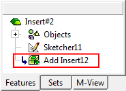
|