|
|
Assembly Radial Array  : Options and Results
Access: Open this function from one of the following locations:
-
Click the
 button in the
toolbar.
 -
Select Assembly > Copy > Assembly Radial Array from the menu bar.
Copy components in a radial array.
Create arrays of components in a radial pattern about a specified axis.
Required Step 1 
Pick the components to be copied.
|
|
|
Required Step 2 
Select the axis of rotation.
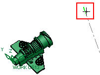
Use MMB to <exit><exit> when the points are selected.
Required Step 3 
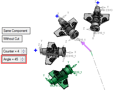
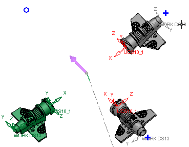
Set the parameters of the array. Note that direction arrows are displayed; click an arrow to flip the direction of the array axis.
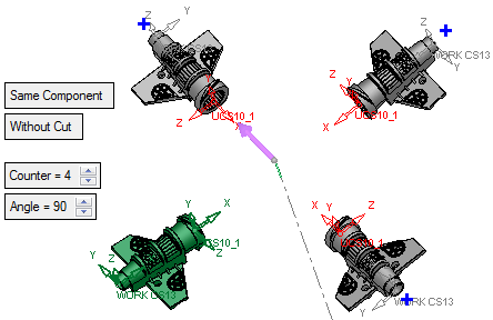
|
Same Component |
Set the Same Component / Different Component toggle options as appropriate. |
|
Without Cut / With Cut |
Set the With Cut / Without Cut toggle option as appropriate. If the With Cut option is selected, the Cut Manager is displayed in the optional step 2. |
|
Counter |
The total number of components after copying, including the original. |
|
Angle |
Set the angle between the copied components.
|
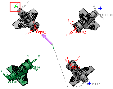
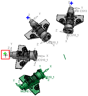
Adjacent to each copied component in the array is a + symbol that is used to turn the copy on or off (to create it or not). Click a + symbol to turn a copy off; the + is replaced with a O symbol. Clicking this O symbol re-displays the copy and the + symbol.
An array must have at least one copied component; if you turn the last copied component off, the OK ![]() button in the Feature Guide is dimmed and is not available.
button in the Feature Guide is dimmed and is not available.
|
Click the + symbol to turn the instance off. |
Click the O symbol to re-display the instance. |
|
|
|
Optional Step 1 
Set the offset and rotation parameters for each instance in the array.
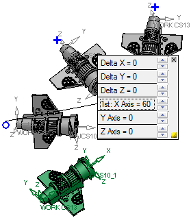
Adjacent to each component instance in the array is a + symbol that provides control the local offset and rotation parameters for that instance.
- Click a + symbol to display and set the offset and rotation parameters for that instance; the + is replaced with a O symbol.
- To cancel the offset and rotation settings for a component instance, click the X button on the top right corner of the parameter box.
- To hide the parameter box, click the yellow box at the bottom right corner of the parameter box; this is similar to the operation of the Dimension Box.
When dragging geometry along an axis, or rotating around an axis on screen, the Triad symbol is displayed.
Example:Example:
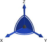
The Triad allows dragging in 3D, along the X, Y, and Z axes or on the XY, XZ and YZ planes (as well as free dragging). It also allows rotation dragging around each one of the axes (X axis, Y axis, or Z axis). The Triad Data Pane is displayed when dragging or rotating objects, providing real-time delta movement information.
|
Click the + symbol to display the local offset and rotation parameters. |
Set the parameters as required. |
|
|
|
Optional Step 2 
The Cut Manager is displayed if the With Cut option is selected in step 3; select the parts to be cut. This step provides manual control over which parts are to be cut.
Click OKOK or ApplyApply in the Feature Guide to complete the function.
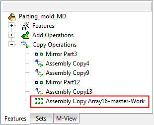
When completed, the Assembly Copy Array feature will appear in the Feature Tree as follows:
|


