|
|
CMM (XYZ Labeling) > Attach Labels  : Options and Results

Access: Activate the appropriate part/electrode and then select Tools > Tools > Attach Labels (CMM) from the menu bar.
Attach XYZ coordinate information (3 or 5 axes) to geometry and different parameters for CMM measurement.
This function consists of the following steps:
Required Step 1 
Define the parameters for each group of parts to be measured.
If points are already assigned, this step is skipped when the function is invoked. In this case, the function opens at the required step 2. However, you can select this step if required.
The Groups dialog is displayed:
|
CMM Type = Electrode: |
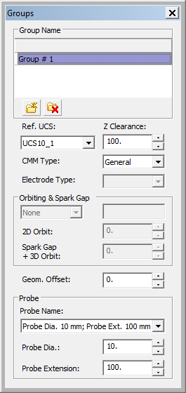
CMM Type = General: |
|
|
|
|
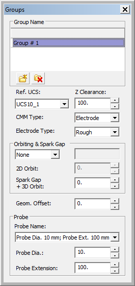
Dialog Parameters
Set the parameters for each group. Some of the Groups dialog parameters can also be defined in the EDM Electrode Setup; see below.
|
Group Name |
Displays the names of the available groups of parts (in the example above, only one group is displayed - Group #1). Groups contain various features that define them. New groups can be added; existing groups can be renamed, modified, or deleted. The parameter settings of the selected group are displayed in the lower sections of the dialog. |
|
Ref. UCS |
All the values of the selected points and the clearance plane are calculated using the location and orientation of this UCS. |
|
Z Clearance |
Defines the location of the clearance plane. |
|
CMM Type |
The following types of CMM are available from the dropdown list:
|
|
Electrode Type |
This dropdown box is grayed out when the CMM Type is General. The following electrode types are available:
The default values of the parameters of each option are retrieved from the related data in the EDM Setup. |
|
Orbiting & Spark Gap |
Select the Orbiting Type from the dropdown list. The following options are available:
If Other is selected, enter the type in the adjacent field. |
|
2D Orbit |
If an electrode is measured, the Cimatron model represents the geometry that must be removed (burnt) and not the actual geometry/size of the manufactured electrode. In order to select points on Cimatron's model that correspond with the actual size of the manufactured electrode, the Orbit Value (2D offset due to 2D orbit) should be determined. |
|
Spark Gap + 3D Orbit |
If an electrode is measured, the Cimatron model represents the geometry that must be removed (burnt) and not the actual geometry/size of the manufactured electrode. In order to select points on Cimatron's model that correspond with the actual size of the manufactured electrode, the 3D Orbit and Spark Gap Values (3D offset due to 3D orbit and Spark Gap) should be determined. |
|
Geom. Offset |
The global offset from the Part Surface at which machining is performed. A positive offset of the part is considered as a negative geometrical offset for the tool. |
|
Probe Name |
A specific probe can be added for each group. The probe's properties (name, diameter, extension length) can either be predefined in the CMM (XYZ_Labeling) feature's optional stage or changed in this dialog. |
Dialog Buttons
Use the following buttons to create and delete groups:
|
|
Add a new group. The new (default) group name is immediately displayed together with default parameter settings in the lower sections of the dialog.
|
||||
|
|
Delete an existing group. Select the group to be deleted and press the Delete Group button. The group is deleted from the Group Name pane. |


Renaming Groups
Existing groups can renamed. The group name is changed, but the parameter definitions are unchanged.
For example:
|
To rename a group . . . |
double-click a group name and rename it . . . |
as required. |
|
|
|
|
Using the EDM Setup Parameters
Some of the Groups dialog parameters can also be defined in the EDM Electrode Setup.
For example:For example:
|
In the EDM Setup for electrodes, if the parameter values in the Rough technology section are set to the following: |
When the CMM (XYZ Labeling) > Attach Labels is re-invoked, the CMM is now recognized as an Electrode Type. The values of the electrode type are retrieved from the relevant EDM Setup parameters. |
|
|
|
As shown in the example above, some of parameters that are defined in the EDM Setup also appear in the CMM Groups dialog. If any of these parameters is subsequently changed in the Groups dialog, the parameter is displayed in red to indicate that the value is different from the relevant value in the EDM Setup.
For example:
|
Group dialog parameter values retrieved from the relevant EDM Setup parameters. |
If one of these values is changed in the Group dialog, it is displayed in red to indicate that the value is different from the relevant value in the EDM Setup. |
|
|
|
Although the probe's settings were predefined, they can still be changed at this stage. Any change to the probe's settings in this dialog will only affect the probe used in this group and not the probe's original settings.
Required Step 2 
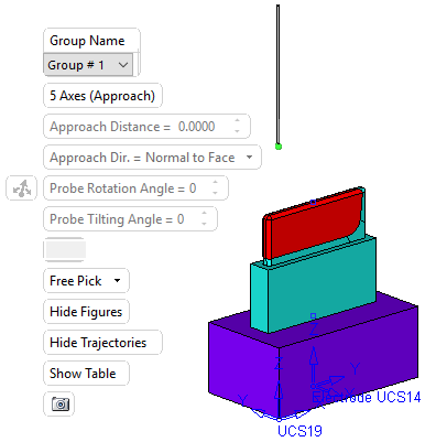
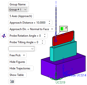
Pick a point on a face and then <exit><exit> to approve it. When a point to be measured is selected, the probe is positioned at the selected point.
The following screen parameters are displayed together with the part and the defined probe.
|
Pick a point on a face to indicate a point to be measured. |
When a point to be measured is selected, the probe is positioned at the selection point and the screen parameters (Approach Distance, Probe Rotation, etc.) can now be modified. In addition, a label is displayed (see below) and also an arrow (click on the arrow to change the probe's direction). |
|
|
|
Press <exit><exit> to approve the point's location. The point's coordinates and all other settings of the feature are now updated in the table of the probe's movement (see the Hide/Show Table parameter explanation below).
Set the parameters as required:
|
Group Name |
The group name as defined in the first required step. However, you can select the required group from the dropdown list which lists all the defined groups. |
||||||||||||||||||
|
5 Axes (Approach) |
If required, switch to 3 axes mode by clicking the 5 Axes (Approach) button. When selecting the 3 Axes (No Approach) option, all the options related to the probe's approach direction or rotation are not available.
|
||||||||||||||||||
|
Approach Distance |
Define the probe's approach distance.
|
||||||||||||||||||
|
Approach Dir. |
Select the required approach direction from the dropdown list:
|
||||||||||||||||||
|
Probe Rotation Angle |
Set the rotation angle of the probe either by entering the angle directly by using the arrow buttons or graphically using the |
||||||||||||||||||
|
Probe Tilting Angle |
Set the probe tilt angle either by entering the angle directly or by using the arrow buttons.
|
||||||||||||||||||
|
<Attribute(s)> |
If required (and if they are defined), select the required attributes from the dropdown list. These attributes can be defined in the second optional step of this function. |
||||||||||||||||||
|
Free Pick |
From the dropdown list, select the method by which to pick points in order to position the probe. The available options are:
|
||||||||||||||||||
|
Hide/Show Figures |
Toggle button to hide or show the figures (labels) that are displayed at every point picked to be measured.
|
||||||||||||||||||
|
Hide/Show Trajectories |
Toggle button to hide or show the probe trajectory displayed at every point picked to be measured.
|
||||||||||||||||||
|
Hide/Show Table |
Toggle button to hide or show the table of the probe's movementstable of the probe's movements.
|
||||||||||||||||||
|
|
Add a picture for the CMM Report. |
 button and then using the

Table of the Probe's Movements
This table is hidden or displayed by using the Hide/Show Table toggle button in the screen parameters. The table displays the coordinates and all other settings of the selected points. See the explanation of the buttons for ways of how to use this dialog.
The level of precision displayed in the dialog can be controlled by selecting the required precision from the dropdown list.
For example:For example:
Dialog Buttons
Use the following buttons to create and delete groups:
|
|
Show all the columns in the table. Columns can be hidden by right-clicking the column header and selecting the Hide option.
|
|
|
Select point to be edited, either by selecting the number on the appropriate label or by selecting the index number (in the table) that corresponds to the label number to be edited. Use the |
|
|
Simulate the probe's movement to the previous point. |
|
|
Simulate the probe's movement to the previous step. |
|
|
Simulate the probe's movement to the next step. |
|
|
Simulate the probe's movement to the next point. |


Optional Step 1
Define the parameters of the probe.
New probes can be added; existing probes can be renamed, modified, or deleted. The parameter settings of the selected probe are displayed in the lower sections of the dialog.
The Probe dialog is displayed.
|
|
All changes done here are also reflected in the Probe section of the Groups dialog in the first step.
For example:For example:
|
A new probe, together with its parameters, is defined in the Probe dialog. |
When saved in the Probe dialog, the new probe is displayed in the dropdown list of available probes in the Groups dialog. |
Selecting the new probe in the Groups dialog also displays its parameters. |
|
|
|
|
Dialog Parameters
Set the parameters
The following parameters can be defined for each probe:
|
Probe Dia. |
Set the diameter of the probe - see the examples below. |
|
Probe Extension |
Set the length of the probe's extension - see the examples below. |
Examples:
|
Probe Dia. = 11 |
Probe Dia. = 3 |
|
|
|
Dialog Buttons
Use the following buttons to create, save, and delete probes:
|
|
Add a new probe. The new (default) probe name is immediately displayed together with default parameter settings in the lower sections of the dialog.
|
||||
|
|
Save the selected probe and its parameter settings. |
||||
|
|
Delete an existing probe. Select the probe to be deleted and press the Delete Probe button. The probe is deleted from the Probe Name pane. |


Renaming Probes
Existing probes can renamed. The probe name is changed but the parameter definitions are unchanged.
For example:
|
To rename a probe . . . |
double-click a probe name and rename it . . . |
as required. |
|
|
|
|
Optional Step 2
Define additional attributes.
New probes can be added; existing probes can be renamed, modified, or deleted. The parameter settings of the selected probe are displayed in the lower sections of the dialog.
The Point Attributes dialog is displayed, which enables you to define up to ten attributes:
|
|
All changes done here are also reflected in the Probe section of the Groups dialog in the first step.
For example:For example:
|
In this example five attributes are defined. |
If you define just one attribute . . . |
|
|
|
|
|
|
|
|
|
|
These attributes are displayed as screen parameters in the second required step of the function. |
This one attribute is displayed as a screen parameter. |
|
|
|
|
Dialog Buttons
Use the following buttons to create, save, and delete attribute values:
|
|
Save the defined attributes and values. |
|
|
Add a new row of attribute values in the lower pane of the dialog.
|
|
|
Delete a row of attribute values in the lower pane of the dialog. This button is only displayed if an attribute value exists in the lower pane. |
|
|
Move a row of attribute values up or down. This button is only displayed if more than one row of attribute values exists in the lower pane.
|
|
|


Renaming Attributes
Attributes can renamed. The attribute name is changed, but the parameter definitions are unchanged.
For example:
|
To rename a attribute . . . |
double-click an attribute name and rename it as required. |
|
|
|
When finished, press OK ![]() or Apply
or Apply ![]() in the Feature Guide to complete the function.
in the Feature Guide to complete the function.
If required, create a CMM report containing the measuring data results.
|