|
|
Cookie  : Options and Results
Access: Open this function from one of the following locations:
-
Select Wireframe > Modify Curves > Cookie from the toolbar.
-
Select Die Design > Strip Tools > Cookie from the menu bar.
-
Select Cookie from the following Die Design Guide: Strip Design.
In Cimatron, a Cookie is an automatic curve offset and extension. Cookies are especially useful in die design and strip development because they quickly automate the overlap of punch areas; however, the Cookie function has many applications outside of die design. For example, for clearing pocket corners or creating contours for Wire EDM. Cookies can either extend an entire edge or just act in selected corners. Several options in the Cookie function provide complete control over every aspect of the shape and offset distance.
Required Step 1 
-
Pick a planar wire or a face.
Use the Single screen parameter to toggle between the Single or Multi (use only with "By Point") options that allow you to select one or multiple planar wires or faces.
Single /
Multi (use only for "By Points")Single
Pick a planar wire or a face. This is the default option.
ExampleExample
The next step (Required Step 2) is displayed automatically.
Multi (use only for "By Points")
Pick multiple planar wires or faces.
The Multi option is used together with the By Points option (in Required Step 2) to select multiple entities and to relief all the internal sharp corners at once.
After picking all entities, press <exit><exit> to proceed to the next step (Required Step 2). The multiple planar wires or faces can either be picked individually or By Box.
Notes:
-
The wires/faces cannot be on the same plane.
-
If more than one wire or face is selected, only the By Points option is available in Required Step 2 (for picking sharp corners).
-
Required Step 2 
-
One of the following groups of parameters are displayed. (Toggle between By Points and By Edges to display the appropriate parameters.) Depending on the option selected, either pick a sharp corner or pick the edge(s) from which you wish to create a cookie.
By Points parameters
This is the default toggle option.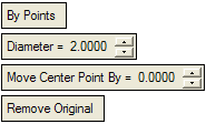
The By Points option is a cookie used to relief internal corners of pockets for Mold sliders and inserts or pockets for die plates. If this option is selected, pick a sharp corner from which to create the cookie.
ExampleExamplePocket with internal sharp corners
Pocket with cookies
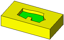
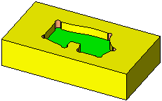
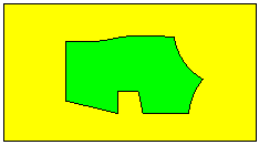
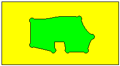
The By Edges option is a cookie (or overcut) used as a method in Die manufacturing that allows users to achieve sufficient overlapping between two adjacent trimming punches. If this option is selected, pick the edge(s) from which to create the cookie.
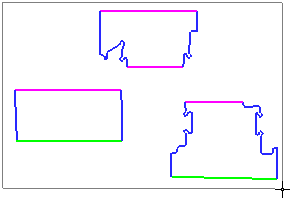
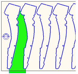
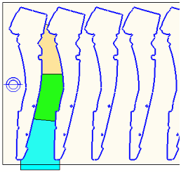
ExampleExampleThe strip shown below requires a punch on the GREEN area.
However, since such a punch is too large, it is necessary to create two or three adjacent trimming punches.
Notes:
-
If more than one wire or face is selected in Required Step 1, only the By Points option is available in this step.
-
If you edit a cookie(s) created using the By Edges parameters and subsequently select multiple wires or faces, all the By Edges parameter settings are cleared and only the By Points parameters will be available.
When the sharp corner/edge(s) is selected, a preview of the cookie is displayed. This preview reflects the options selected and the defined parameters settings. In addition, when an edge is selected, the preview also enables you to control the shape of the cookie by accepting or rejecting cookie flags,.
When an edge is selected, a cookie flag is automatically displayed at both ends of the edge. The default option is to accept all cookie parameter settings at both ends.
If required, click a flag to toggle it to reject all cookie parameter settings (except Offset Value).


By Points parameters
The By Points option is a cookie used to relief internal corners of pockets for Mold sliders and inserts or pockets for die plates.

By Points
This is a toggle option: By Points / By Edges.
By Points: Create a cookie(s) by picking points. Pick one or more sharp vertices on the input wire (face).
In the example below, only the vertices with the RED circle are potential candidates for selection (the other vertices are smooth).
ExampleExample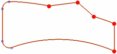
Of the sharp vertices, only those that create an angle larger than 180° on the outer side of the closed wire are selected. For example, in the example below, all the GREEN sectors have more than 180° (outer angle) and only their vertices will be selected (the RED sector vertices are not selected).
ExampleExample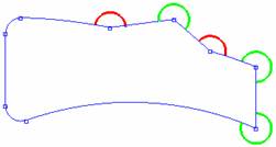
The result in this case (if all 3 sharp vertices with a > 180° outside angle are selected) is the outer contour that was created as if we were merging the bounded face of the original wire with the circle (see the Diameter example below).
Diameter
Define the diameter of the circles that will be created on each of the selected vertices.
ExampleExample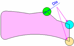
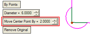
Move Center Point By
Define the distance to move the center point of the circles created on each of the selected vertices. The direction of movement for each center point is towards the inner angle, and the angle of movement is half the inside angle of the vertex. In other words, if the inside angle of a vertex is 170°, the center point of the circle would be moved the defined distance at an angle of 85°. A negative angle value cannot be given.
ExampleExample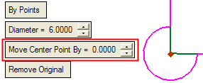
Remove Original /
Keep OriginalThis is a toggle option: Remove Original / Keep Original.
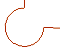
ExampleExampleRemove Original
Remove the original wire entity.
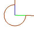
Keep Original
Keep the original wire entity.
By Edges parameters
The By Edges option is a cookie (or overcut) used as a method in Die manufacturing that allows users to achieve sufficient overlapping between two adjacent trimming punches.

By Edges
This is a toggle option: By Points / By Edges.
By Edges: Create a cookie(s) by picking edges. Pick a single edge and the system automatically selects all "smooth" edges to the picked edges.
Circle
Dropdown list containing the following options.
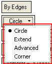
Option DefinitionsOption Definitions
Circle
Create a rounded cookie with a diameter value parameter setting.
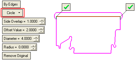
Using this option:
-
If the Offset Value > 0, the selected edges are offset and trimmed/extended with the side edges (as described below for Extend).
-
Two circles are created.
-
Rounds are added if the Radius > 0.

Extend
Create a extended cookie with a draft angle value parameter setting.
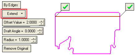
Using this option:
-
The selected edges are offset outside by the Offset Value parameter (using sharp edge - linear extension).
-
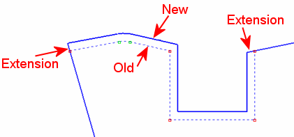
The side edges are linearly extended.
-
The offset and linear extensions are trimmed/extended.
-
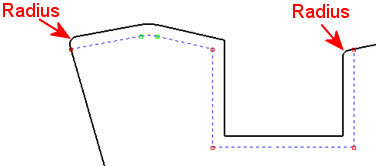
Rounds are added if the Radius > 0.
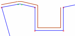
In the example below, the RED edges are selected.
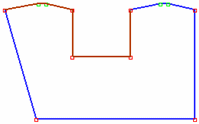
All the selected edges are offset by the required Offset Value.
The side edges are extended linearly to the offset edges.
If a Radius is defined (> 0), the result would be as follows:
Notes:
-
If the Offset Value = 0, the radius is created on original sharp vertices (edges).
-
If the Offset Value = 0 and Radius = 0, the function complete the operation but no change occurs.
Advanced
Create a cookie with advanced parameter settings.
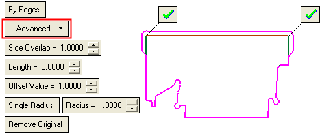
Using this option:
-
Similar to the Circle option, however, instead of a circle, a trimmed offset is created.
ExampleExample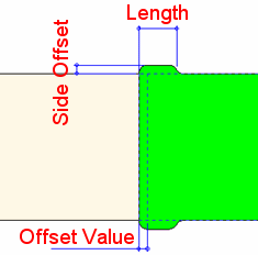
-
Enables you to define multiple radius values for the cookies. In this case, the Radius parameter is replaced with the Single Radius / Multi Radius toggle parameter.
ExampleExample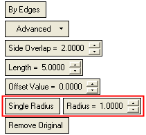
Single Radius produces the same results as the Radius parameter (see below).
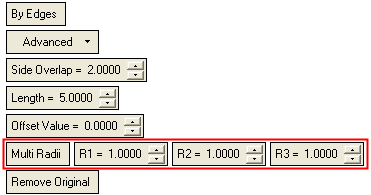
Multi Radius enables you to define multiple radius values for the cookies.
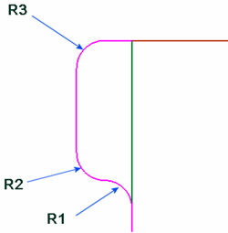
Corner
Create a rounded cookie with a corner radius value parameter setting.
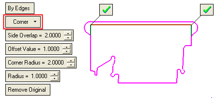
Using this option:
-
The Corner Radius can be defined (see the Corner Radius parameter below).
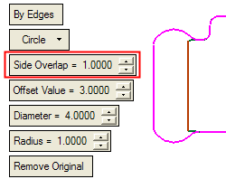
Side Overlap
This parameter appears under the Circle and Advanced options.
Define the side offset from the picked edge(s).
ExampleExample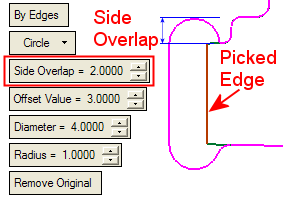
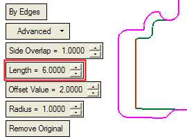
Length
This parameter appears under the Advanced option.
Set the length of the cookie if required.
ExampleExample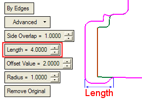
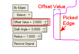
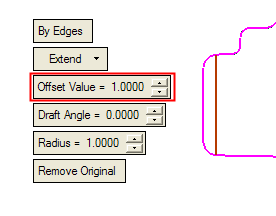
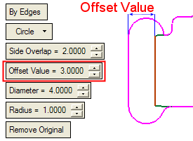
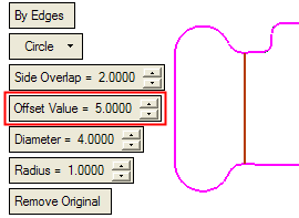
Offset Value
This parameter appears under all the options: Circle, Extend, Advanced, and Corner. Define the offset from the picked edge(s); negative offset values can be applied.
Draft Angle
This parameter appears under the Extend option. Set the draft angle if required.
ExampleExample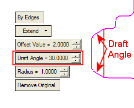
Note: This option is disabled if a negative or zero offset value is applied.
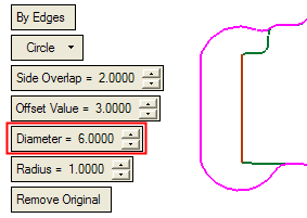
Diameter
This parameter appears under the Circle option. Set the diameters of the circles at either end of the offset.
ExampleExample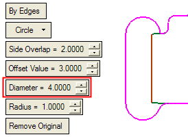
Corner Radius
This parameter appears under the Corner option. Define the corner radius value.
ExampleExampleCorner Radius = 2
Corner Radius = 3
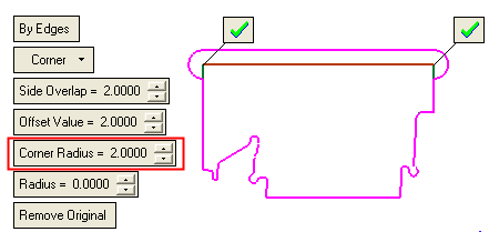
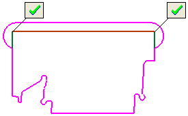
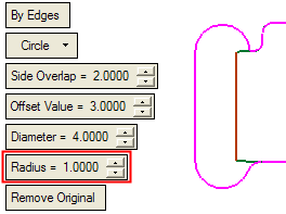
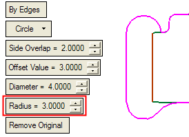
The image below shows the difference between Corner Radius and Radius. Compare this picture with the one above.
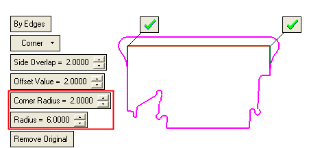
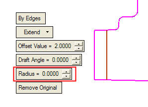
Radius
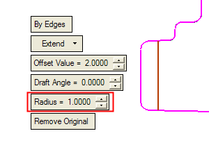
This parameter appears under all the options: Circle, Extend, and Advanced. Define the radius value.
Remove Original
This toggle option appears under all the options: Circle, Extend, and Advanced.
See the explanation under By Points parameters.
-
Optional Step 1 
-
You can add radii at the remaining sharp edges of the new wire created after you completed the Required Step 2. Small hexagons appear on these sharp edges.
The available options from the dropdown list are:


Set the parameters as required.
None
Do not create radii.
Add Radius
Add radii. The following parameter is displayed:
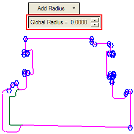
Global Radius
Set a global radius for all the remaining sharp edges of the new wire.
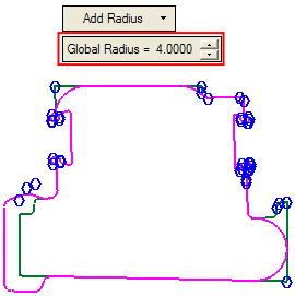
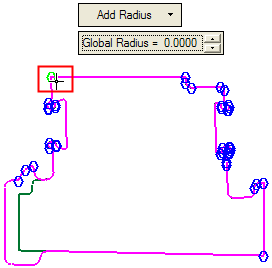
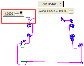
Either set a global radius for all the sharp edges or pick the hexagons on the sharp edges where you wish to set a specific radius. In the latter case, a dimension box appears at each picked hexagon displaying the radius value.
Global Radius set to 0.
Global Radius set to 4. The radii of all the sharp edges are affected; they all have the same radius.
To set a radius for a specific sharp edge, pick the appropriate hexagon and...
set the required radius value. Only the selected edge is affected; it acquires the defined radius value.
-
Click OKOK or ApplyApply in the Feature Guide to complete the function.
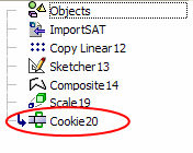
When completed, the Cookie feature will appear in the Feature Tree.
|


