|
|
Die Forces  : Options and Results
Access: Open this function from one of the following locations:
-
Select Die Design > Tools > Die Forces from the menu bar.
-
Select Tools > Die Forces from the following Die Design Guide: Die Tool Design Guide.
Calculate, display, and manipulate die forces.
Within the Die Forces function, the precalculated die forces are shown, the sum of all forces are indicated and so is the point of moment equilibrium. You can type in values other than those automatically calculated and use optional stages, to combine a few forces together, or attach new forces to selected geometry.
This covers the DieDesign / Forming Shape and the tool environments. Forces are calculated in the background of the following forming shape environment operations:
-
The force value is calculated and stored for usage inside the Die Forces function.
This function uses a finite element enginefinite element engine.
The Finite Element Analysis (FEA) engine used in the DieDesign application is based on technology supplied by the Forming Technologies Inc (FTI) 3rd party engine. For additional information on FTI, see www.forming.com.
The finite element engine is used in the following functions:
Whenever the finite element engine is used, resultant forces are calculated and stored for usage in the Die Forces operation.
Force Calculation: The force calculation employed depends on the type of operation being calculated. For additional information and to define some of the values used in force calculations, see the Die Force Calculation Preferences.
Correction Factor: A Die Preference option enables the setting of a default Correction Factor to manipulate forces calculated by the finite element engine. The forces displayed in the above mentioned functions will be multiplied by this factor.
Required Step 1 
Automatically display the precalculated forces, type in values, modify parameters. When the function is openedopened, the precalculated forces are automatically displayed, for example:
-
Edit parameters, modify values, or drag box boundaries to indicate the participating forces.
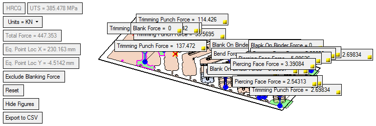
The system generated screen parameters (the ones that are displayed dimmed), show the type of material used, ultimate tensile strength (UTS) of the picked material, the sum of the die forces and the location of the equilibrium point:
User-defined screen parameters are:Units
This determines the units of force value. Options are as shown (for metric and inch unit files). Default force units are Kilo Newton (KN) for metric and Libra forces (Lbf) for inch files. This also determines the (system generated) Total Force value.
Units of force for mm files:
Units of force for inch files:


Include Blanking Force / Exclude Blanking Force
Toggle between these options to include or exclude the blanking force from the force calculation.
Reset
Resets all definitions as they were when the function was opend, i.e. resets all the original values, restores deleted forces, cancels combination of forces and also deletes newly added forces.
Hide Figures / Show Figures
A toggle button to show or hide all force value figures.

When the
 button (in the figures
  ) is clicked, the value is hidden. Restore the value by clicking Show Figures. Irrespective of the hide/show status, the arrow figure is still displayed.
Export to CSV
Display the layout of the forces along the click by exporting the data to a CSV file. This file displays the force value and its position (by XYZ coordinates).
Example:Example:In the CSV file, the XYZ is the location of the force (in the file's units (mm/inch)) and the Force is displayed in the defined force units.
The table is sorted according to the X column (small to large).
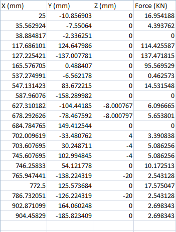
When this option is selected, the system displays the Save As dialog enabling you to save the .CSV file.
A progress bar is displayed while the forces are calculated.
- You can overwrite calculated values by typing the required value into the appropriate field.

All calculations are instantly modified according to the new value and the arrow color changes to indicate that the default value has been changed, as shown:

- Right-click an arrow to display the following menu:

The following popup options are displayed:
Restore Value
Restore the original calculated value, if you changed it. The color of the arrow reverts back to blue and the total force and moment calculation are modified accordingly.
Show Figure
Restore the force figure if it is hidden. This option is disabled when the figure is shown.
Delete
The force is deleted; it is not shown on the screen and ignored in all calculations (this is valid only for new forces created in the optional stage).
Optional Step 1 
Add new forces.
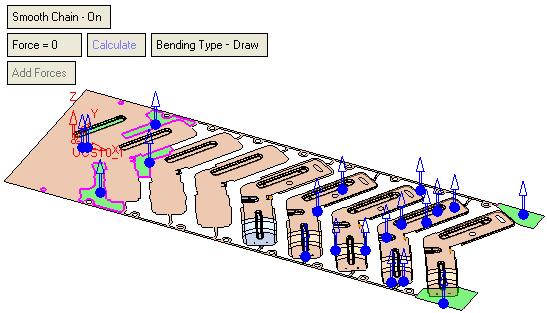
- Pick the stitched faces, calculate or type a value and then click the Add Forces button. When new forces are calculated, a finite element engine is used. The following parameters are displayed:
-
Pick a face and click the Add Forces button to display a bounding box and a force figure (arrow) - (it is also possible to pick contours and edges and calculate the trimming force according to the length of the selected contour/edge). The force point of origin is at center of the bounding box for the picked entity. No value boxes are displayed while in the Optional Step 1 stage: the relevant value boxes are only displayed when you return to the Required Step 1 stage. See the Note below regarding selecting more than one group of faces.
The following options are displayed:Smooth Chain On / Smooth Chain Off
This is a toggle option, Smooth Chain On / Smooth Chain Off:
he system automatically identifies (and selects) all the adjacent smooth faces.
Force
Manually set a force value. If a force is added (by clicking the "Add Forces" button), without previously clicking "Calculate", the value for the added force is taken from this Force field.
Calculate
Calculate the dimple forming force. This runs the finite element engine to calculate the force with the defined parameter settings.
If you selected contours and edges, this option calculates the trimming force according to the length of the selected contour/edge.
Force Calculation: The force calculation employed depends on the type of operation being calculated. For additional information and to define some of the values used in force calculations, see the Die Force Calculation Preferences.
Moment Calculation: A special figure (
 ) is drawn on the strip face at the moment point of equilibrium location.
See the Note below regarding selecting more than one group of faces.
Bending Type - Form
This parameter is displayed when picking a non-planar face (or groups of faces) and is used to calculate the force with the defined parameter settings. This is a toggle option Bending Type - Form / Bending Type - Draw.
See the parameter explanations in the Blank Tool, where these parameters also appear.
Trimming Punch Force
This parameter is displayed when picking a planar face (or groups of planar faces in the same plane) or a contour, and is used to calculate the trimming force with the defined parameter settings. This parameter appears dimmed.
Add Forces
Add forces, based on parameter settings, to the selected entities. This parameter is dimmed until a face, contour or edges is selected.
Note: When selecting more than one group of faces, the following message is displayed after clicking the Calculate button:
"Note that when selecting more than one group of faces, the resulting force for all the groups will be the same as the first picked group."
You are then prompted to click OK to allow the calculation. See the images below.If the selected faces are adjacent and stitched, they are considered to be attached to the same force. 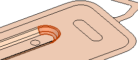
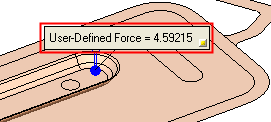
If a single entity is selected, the displayed force value is that of the selected entity. 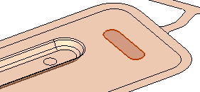
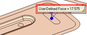
If multiple groups of disconnected or unstitched faces are selected, then a separate force is attached to each group of faces, and the resulting force values for all the groups are the same as the force value of the first picked group. 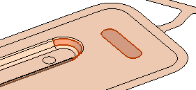
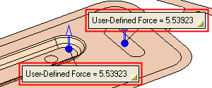
Optional Step 2 
Copy force figures to new locations. The new forces are included in all relevant total force and moment calculations.
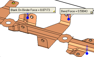
-
Pick the force figures to be copied and set the parameters. The copied force figures (arrows) are displayed in blue while you are setting the parameters.
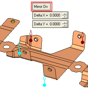
Mirror On
Mirror the picked forces about the center of the strip. Set the Delta X and Delta Y distances as required, to position the blue colored copy.
Mirror Off
Set the Delta X and Delta Y distances as required, to position the blue colored copy.
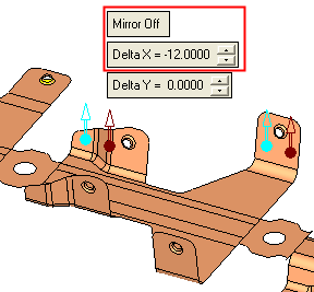
Delta X / Delta Y
Define the Delta X and Delta Y distances from the picked forces.
- When you return to Required Step 1, the new forces are added as shown:
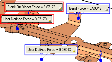
The new forces are included in all relevant total force and moment calculations. - Click OK
 in the Feature Guide to complete the function.
|
