|
|
Direct Modeling  : Options and Results


Access: Open this function from one of the following locations:
-
Click the
button in the toolbar. -
Select Solid > Main Tools > Direct Modeling from the menu bar.
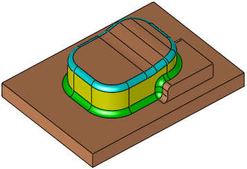
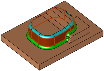
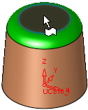
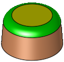
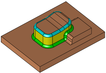
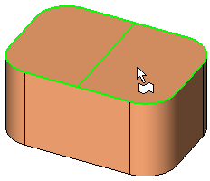
Modify the model directly, by modifying and manipulating part features without editing their parametric features. The function directly manipulates selected faces while retaining the features of adjacent faces.
Required Step 1 
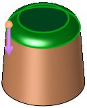
Pick the faces and then <exit><exit>.
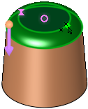
Required Step 2 
Select the type of operation to be performed, pick the required entities (where relevant - depending on the operation) and define the parameters.
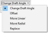
Select the operation from the dropdown list; depending on the selection, one of the following sets of parameters is displayed:
|
|
|
|
|
|
|
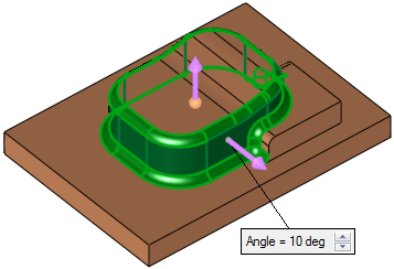
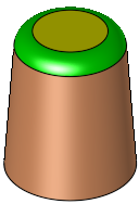
Change the draft angle of the selected faces. |
|
|
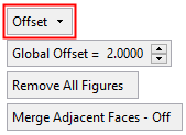
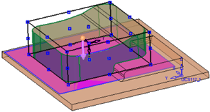
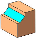
Offset the selected faces by a general (Global) offset (pick faces to set specific offset values) and indicate the offset side (via a direction arrow). |
|
|
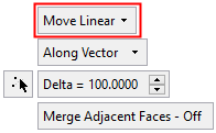
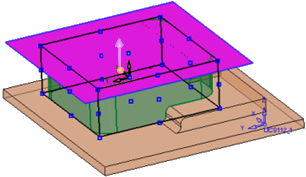
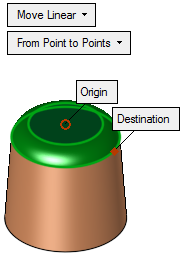
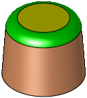
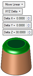
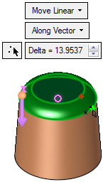
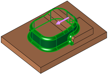
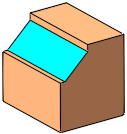
Linearly move the selected faces. |
|
|
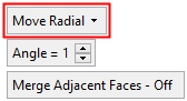
Radially move the selected faces around a displayed axis. |
|
|
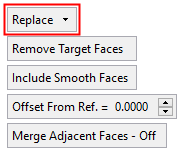
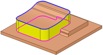
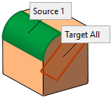
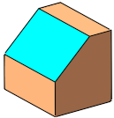
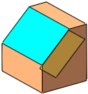
Replace the selected (source) faces with target faces. |
Note: The round faces are automatically added to the operation at this step. Use the Optional step to pick additional faces or to unpick automatically selected faces.
Operation Options
|
Change the draft angle of the selected faces.
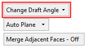
From the dropdown list, select the option to define the reference plane from which the draft angle is to be created:
|
|||||||||||||||||||||||||||||||||||||||||||||||||||||||||||||||||||
|
Linearly move the selected faces. This interaction for this option is the same as the Extend Object > Move Linear option. The following Move Linear options are available:
|
|||||||||||||||||||||||||||||||||||||||||||||||||||||||||||||||||||
|
Radially move the selected faces around a displayed axis. This interaction for this option is the same as the Extend Object > Move Radial option.
|
|||||||||||||||||||||||||||||||||||||||||||||||||||||||||||||||||||
|
Offset the selected faces by a general (Global) offset (pick faces to set specific offset values) and indicate the offset side (via a direction arrow). This interaction for this option is the same as the Extend Object > Offset option.
Additional Example:Additional Example:
|
|||||||||||||||||||||||||||||||||||||||||||||||||||||||||||||||||||
|
Replace the selected (source) faces with target faces. This interaction for this option is the same as the Extend Object > Replace option.
Note: For the Replace option, a maximum of 20 faces can be selected in step 1. If more than 20 faces are selected, a warning message is displayed and the Replace option cannot be selected; the other options are still available. |
|||||||||||||||||||||||||||||||||||||||||||||||||||||||||||||||||||
Parameters
|
Delta |
The distance the selected faces are to be moved linearly in the defined direction. |
||||||
|
Angle |
The angle which the selected faces are to be moved around a displayed axis. |
||||||
|
Global Offset |
Set the global offset value for selected faces. In addition, local offset values can be defined by selecting faces and entering the offset value in local offset labels. |
||||||
|
Remove All Figures |
Remove (hide) all local offset labels to improve clarity. |
||||||
|
Remove Target Faces |
This is a toggle option that enables you to either keep or remove the target faces from the result. Toggle options: Remove Target Faces / Keep Target Faces.
Note: This parameter is grayed out and displays the option Keep Target Faces in the following cases:
|
||||||
|
Include Smooth Faces |
This is a toggle option that enables you to either include or exclude smooth faces from the result. Toggle options: Include Smooth Faces / Don't Include Smooth Faces.
|
||||||
|
Offset from Ref. |
Add an offset value from the reference face, when defining the target face. The offset is according to the normal of the reference face(s) or the datum plane.
|
|
Merge Adjacent Faces On/Off |
This is a toggle option Merge Adjacent Faces On/Off enabling you to merge the adjacent faces, after the selected face(s) have been removed and the adjacent faces have been extended to fill the gap.
|

In the Offset From Reference option in the Direct Modeling and Extend Object tools, the user can now add an Offset value from the Reference (as in Extrude to Reference), allowing more flexibility in the definition of the target face.
Optional Step 1 
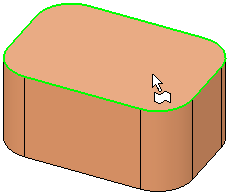
Pick/unpick round faces. Round faces are automatically added when using this function. The optional step enables you to pick additional faces or unpick faces that were found by default.
Click OK ![]() or Apply
or Apply ![]() in the Feature Guide to complete the function.
in the Feature Guide to complete the function.
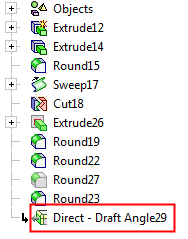
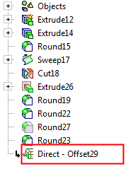
When completed, the Direct - <option> feature will appear in the Feature Tree as follows (where <option> is the function option used to created the feature):
|
Direct Modeling feature, |
Direct Modeling feature, |
|
|
|

|