|
|
Extend Object  : Options and Results


Access: Open this function from one of the following locations:
-
Click the
button in the toolbar. -
Select Solid > Main Tools > Extend Object from the menu bar.
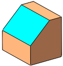
Move faces of a solid object while extending or trimming adjacent faces to keep the object closed.
This function can be used to:
-
Move faces (linearly or radially) while extending adjacent faces.
-
Offset faces while extending adjacent faces.
-
Replace a face (or set of faces) with another face (or set of faces).
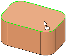
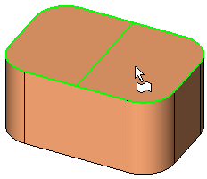
Required Step 1 
and then <exit><exit>.
The face selection mode is automatically set to Picked Faces Only, however, you can set this as required.
Required Step 2 
Define the options and set the parameters for extending the object. The following parameters are displayed by default:
|
|
|
Select the operation from the dropdown list; depending on the selection, one of the following sets of parameters is displayed:
|
|
|
|
|
|
Linearly move the selected faces. |
|
|
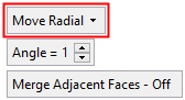
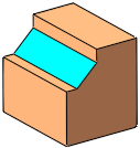
Radially move the selected faces around a displayed axis. |
|
|
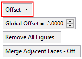
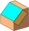
Offset the selected faces by a general (Global) offset (pick faces to set specific offset values) and indicate the offset side (via a direction arrow). |
|
|
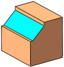
Replace the selected (source) faces with target faces. |
Operation options:
|
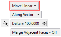
Linearly move the selected faces. The following Move Linear options are available:
|
||||||||||||||||||||||||||||||||||||||||
|
Radially move the selected faces around a displayed axis.
|
||||||||||||||||||||||||||||||||||||||||
|
Offset the selected faces by a general (Global) offset (pick faces to set specific offset values) and indicate the offset side (via a direction arrow).
See the additional examples below. |
||||||||||||||||||||||||||||||||||||||||
|
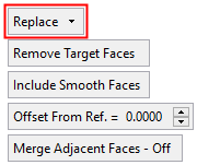
Replace the selected (source) faces with target faces.
See the additional examples below. Note: For the Replace option, a maximum of 20 faces can be selected in step 1. If more than 20 faces are selected, a warning message is displayed and the Replace option cannot be selected; the other options are still available. |
||||||||||||||||||||||||||||||||||||||||
Parameters:
|
Delta |
The distance the selected faces are to be moved linearly in the defined direction. |
||||||
|
Angle |
The angle which the selected faces are to be moved around a displayed axis. |
||||||
|
Global Offset |
Set the global offset value for selected faces. In addition, local offset values can be defined by selecting faces and entering the offset value in local offset labels. |
||||||
|
Remove All Figures |
Remove (hide) all local offset labels to improve clarity. |
||||||
|
Remove Target Faces |
This is a toggle option that enables you to either keep or remove the target faces from the result. Toggle options: Remove Target Faces / Keep Target Faces.
Note: This parameter is grayed out and displays the option Keep Target Faces in the following cases:
|
||||||
|
Include Smooth Faces |
This is a toggle option that enables you to either include or exclude smooth faces from the result. Toggle options: Include Smooth Faces / Don't Include Smooth Faces.
|
||||||
|
Offset from Ref. |
Add an offset value from the reference face, when defining the target face. The offset is according to the normal of the reference face(s) or the datum plane.
|
|
Merge Adjacent Faces On/Off |
This is a toggle option Merge Adjacent Faces On/Off enabling you to merge the adjacent faces, after the selected face(s) have been removed and the adjacent faces have been extended to fill the gap.
|

Offset: Additional Examples
- Changing Plate Width and LengthChanging Plate Width and Length
Pick the side faces and offset them as required
Result: the length and width of the plate has been changed accordingly

- Changing Rib WidthChanging Rib Width
Pick the side faces of the rib and offset them toward the inside or outside, as required.
Result: the width of the rib has been changed accordingly
- Reducing HolesReducing Holes
Pick the faces of the hole and offset them towards the inside, as required.
Result: the size of the hole has been reduced accordingly
- Enlarging HolesEnlarging Holes
Pick the faces of the hole and offset them towards the outside, as required.
Result: the size of the hole has been enlarged accordingly.
Replace: Additional Examples
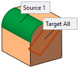
- Replace Example 1Replace Example 1
The source and target faces are selected:
Result: the selected Source 1 face is replaced with the selected Target All face:
- Replace Example 2Replace Example 2
The source and target faces are selected:
Result: the selected Source 1 face is replaced with the selected Target All face, as follows:
- Replace Example 3Replace Example 3
The source and target faces are selected:
The selected Source 1,2,3,4 faces are replaced with the selected Target 1,2,3,4 faces, respectively as follows:
Click OK ![]() or Apply
or Apply ![]() in the Feature Guide to complete the function.
in the Feature Guide to complete the function.
When completed, the Extend Object feature will appear in the Feature Tree as follows:

|