|
|
Layout UCS  : Options and Results
Access: Open this function from one of the following locations:
-
Click
 in the toolbar.
 -
Select Wireframe > Datum > Layout UCS from the menu bar.
-
Select Parting > Layout Tools > Layout UCS from the menu bar.
-
Select Parting Layout Tools > Layout UCS from the Mold Design Guide Toolbar or Parting Guide Toolbar.
Create a UCS to be used as a layout UCS and have work parts placed on it.
Edit a Layout Part. This enables you to edit the pattern of coordinate systems, by changing the location and orientation of a single or multiple UCSs.
Any UCS in the Layout part will be considered a Layout UCS. However, note that using a UCS whose Z direction is not aligned with the mold's Z direction, may cause undesired results in the QuickSplit simulation of parting surfaces.
Required Step 1 
Pick the UCSs to be edited.
Required Step 2 
Set the orientation (rotation) parameters.
Note: To choose different UCSs, clcik the Required Step 1 icon ![]() again, and re-pick the UCSs.
again, and re-pick the UCSs.
These orientation parameters are displayed for the picked UCSs and relate to them globally (any change in the parameters will affect all the picked UCSs). Individual UCSs (within the picked group) can be edited by specifying values that differ from the general values.
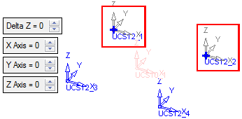
Notes:
-
The initial orientation is parallel to the main layout part coordinate system. These parameters consist of 1 translation (in the Z direction) and 3 rotations.
-
The order of specifying rotations is extremely important and this will be shown in the interaction. For example:
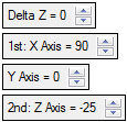
Picked UCS Edit
This enables you to edit all the picked UCSs using global parameter values. In the example below, the X axis has been rotated 90 degrees, affecting the UCSs 12_1 and 12_2.
Note: Picked UCSs are denoted by  .
.
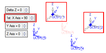
Individual UCS (within picked group) Edit
Individual UCSs (within the picked group) can be edited by specifying values that differ from the general values. These, individually edited UCSs, display their orientation parameters within a dialog box attached to the UCS.
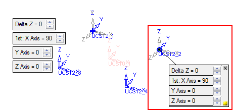
Notes: The initial orientation parameters are the same as those of the (edited) picked UCSs. Individually edited UCSs within a group are denoted by  .
.
Any change in the parameters affect only the individual UCS (from the picked group).
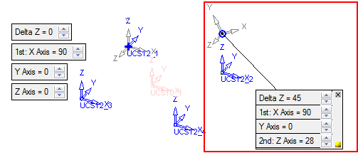
Note: Each orientation parameter dialog box displays the following icons:
|
|
Click this icon to revert the orientation values of the relevant UCS to those of the current values of the picked group. |
|
|
Click this to hide the parameter dialog box of the relevant UCS. The UCS is still denoted by |
When finished, click OK ![]() or Apply
or Apply ![]() in the Feature Guide to complete the function.
in the Feature Guide to complete the function.
|


