|
|
Line : By Direction


Access: Open this function from one of the following locations:
-
Select Wireframe > Main Tools > Line from the menu bar and toggle the first screen parameter in the display area to By Direction.
-
Select Curves > Line from the Strip Design Die Design Guide and toggle the first screen parameter in the display area to By Direction.
Create a line that starts from a point and specify its length and direction (see Picking Points). Create the line on one or both sides of the geometry – either By Delta (by a given value and direction) or By Reference (to a reference face, plane, or point.)
See Line: Options & Results for additional line creation options.
Demo: Press the button below to view a short movie demonstrating the function:

By Line options and definitions
-
Parameter optionsParameter options
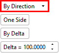
By Delta
By Reference
-
Parameter definitionsParameter definitions
By Direction
Create a line starting from a point of a specified length and direction. See Line: Options & Results for additional line creation options that are available for this toggle screen parameter.
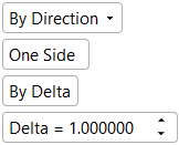
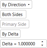
One Side /
Both Sides
Create a line on one side of the picked start point.
Create a line on both sides of the picked start point.
By Delta /
By Reference
Create a line by a given value and direction (on one or both sides).
Create a line to a reference face, plane, or point (on one or both sides).
Delta
Entry parameter for defining the delta value
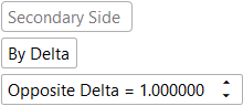
Opposite Delta
Entry parameter for defining the opposite delta value
Offset from Ref.
Entry parameter for defining the distance from the reference geometry
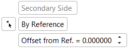
Primary Side
Secondary SideNon-editable screen parameters that indicate the side (primary or secondary) the options/values apply to
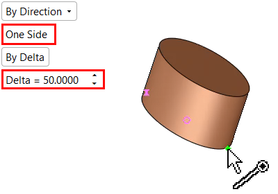
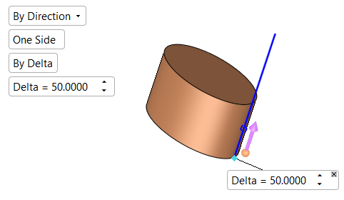
Creating a line on one side
Create a line on one side of the picked start point, define the line's direction, and set its length (delta). (The default value for the Delta parameter is 100 mm).
-
Select Wireframe > Main Tools > Line from the menu bar.
-
The Line Feature Guide appears. Required Step 1
 is automatically activated.
The Line function's screen parameters appear in the display area.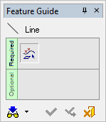
 Tip: You can open the Feature Guide at any time by right-clicking the mouse in the graphic display area.
 -
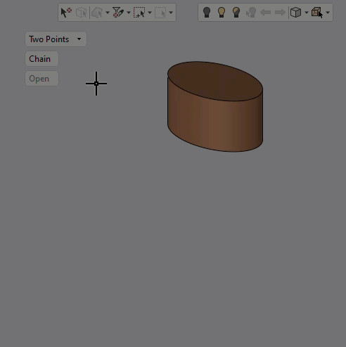
Toggle the Two Points parameter to By Direction.


-
Enter a value for the Delta screen parameter to specify the line's length.
-
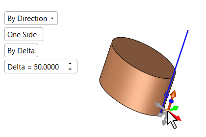
Click the line start point.
-
The line is displayed along with a directional arrow. Click the line to enter a new line length.
-
Click the arrow origin to set the direction of the line.
-
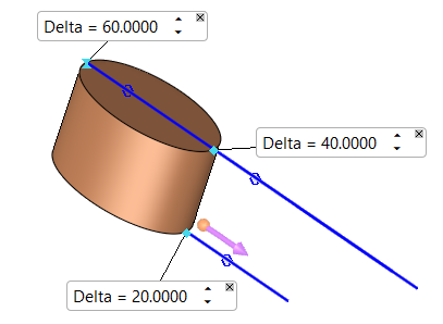
More than one point can be picked to create a number of lines. All lines the are created in one direction defined by the arrow of the 1st point picked. However, the line length value for each line can be changed by clicking on the BLUE CIRCLE
 on the appropriate line.
-
Click OKOK
 or ApplyApply
 in the Feature Guide to complete the function.
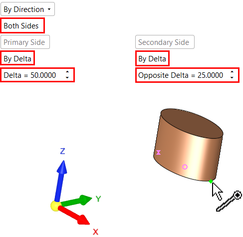
Creating a line on both sides
Create a line on both sides of the picked start point, define the line's direction, and specify its length (delta and opposite delta). (The default for the Delta and Opposite Delta parameters is 100 mm).
Toggle the One Side screen parameter to Both Sides.
-
Follow steps 1 through 3 from Creating a Line on one side.
-
Make sure the toggle option, By Delta, is selected.
-
Enter values for the Delta and Opposite Delta parameters to specify the line length.
-
PickPick the line start point.
-
The lines are displayed together with a directional arrow. The line length, line direction, and multiple line options are the same as for One Side.
-
Click OKOK
or ApplyApply in the Feature Guide to complete the function.
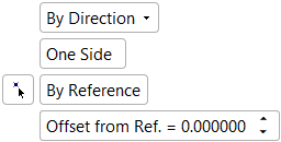
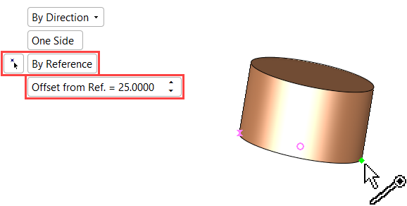
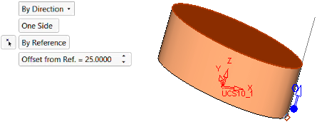
Creating a line on one side of a selected reference entity
Create a line on one side in a given direction to a selected plane, curve, face(s), or point.
-
Follow steps 1 through 3 from Creating a Line on one side.
-
Toggle the By Delta screen parameter to By Reference.
-
Enter a value for the Offset from Ref. parameter to specify the distance of the line from the selected reference (which you will select in step 5).
-
PickPick the line start point.
-
Pick the reference entity. This can be a plane, curve, face(s), or point. If required, use
 to pick a reference point.
 -
The line is displayed the appropriate distance from the reference. In this example, the line extends 25 mm beyond the reference face. Negative values can be entered, in which case the line would extend up to the appropriate distance before the reference.
-
Click OKOK
or ApplyApply in the Feature Guide to complete the function.
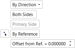
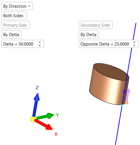
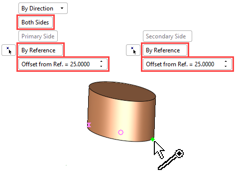
Creating a line on both sides of a selected reference entity
Create a line on both sides (in a given direction) to a selected plane, curve, face(s), or point.
-
Follow steps 1 through 3 from the first section.
-
Toggle the One Side screen parameter to Both Sides.
-
Toggle the By Delta screen parameter to By Reference. You may need to set this parameter for both the Primary Side and Secondary Side, depending on your requirements.
-
Enter a value in the Offset from Ref. parameter to specify the distance of the line from the reference entity (you will select the reference entity in step 5). You may need to set this parameter for both the Primary Side and Secondary Side.
-
Click the line start point.
-
Pick the reference entity. This can be a plane, curve, face(s), or point. If required, use
to pick a reference point.
-
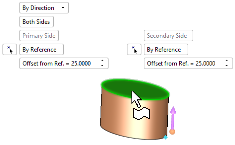
The line is displayed the appropriate distance from the reference. In this example, the line extends 25 mm beyond the reference face in both directions.
-
Click OKOK
or ApplyApply in the Feature Guide to complete the function.
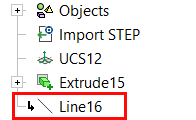
When completed, the Line feature will appear in the Feature Tree.
Notes:
-
Multiple reference faces can be picked (and unpicked).
-
If more than one reference face was picked, the line(s) should intersect at least one face otherwise no line will be created to the specific point.
-
If none of the lines intersect with the picked face(s) (or curve/datum), no lines are created.
-
If a specific line intersects with more that one face (or intersects the same face more than once), the closest intersection point (to the base point) will be considered as the correct result.
-
If the type of reference entity (face(s), curve or plane) is changed, all the reference entities are unpicked (except for the newly picked entity).

|