|
|
Local Blank  : Options and Results
Access: Open this function from one of the following locations:
-
Select Die Design > Geometry Manipulation > Local Blank from the menu bar.
-
Select Local Blank from the following Die Design Guide: Die Process Design Guide (Forming).
Create a flat face out of a set of adjacent stitched faces using finite element analysis (FEA).
The result is dependent on the list of parameters representing the material type and thickness and the 2D boundary conditions. This function uses a finite element enginefinite element engine.
The Finite Element Analysis (FEA) engine used in the DieDesign application is based on technology supplied by the Forming Technologies Inc (FTI) 3rd party engine. For additional information on FTI, see www.forming.com.
The finite element engine is used in the following functions:
Whenever the finite element engine is used, resultant forces are calculated and stored for usage in the Die Forces operation.
Correction Factor: A Die Preference option enables the setting of a default Correction Factor to manipulate forces calculated by the finite element engine. The forces displayed in the above mentioned functions will be multiplied by this factor.
Pick the reference (fixed) face(s) and then pick the faces to blank. Then define the required parameters, such as material type and thickness and the result is a new face with an unfolded area of the selected faces based on the plane defined by the fixed faces, as shown in the example below:
|
|
|
|
Smooth Chain Selection On: In this case when selecting the faces on which to perform the local blank, system will automatically select all the adjacent smooth faces.
Required Step 1 
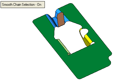
- ExitExit the step.
Required Step 2 
- Pick the required faces to blank (marked in red ). The system automatically identifies (and selects) all the faces adjacent smooth faces. If required, you can deselect these faces manually,
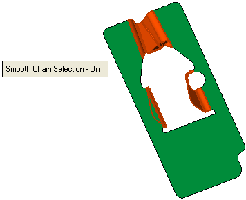
- ExitExit the step.
Required Step 3 
-
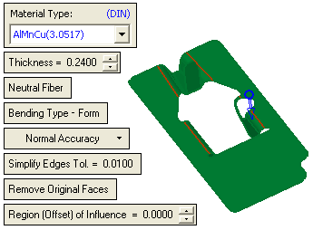
Define the required parameters:
Some of these parameters are common to other functions. See the parameter explanations of these parameters under the Blank function.
In addition to the above parameters, the following parameters also appear in the Local Blank function:Simplify Edges Tol.
Enter the required Simplify Edges Tolerance value. In this case the system attempts to create analytical geometry within the specified tolerance, that is defined here.
Remove Original Faces
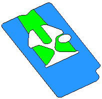
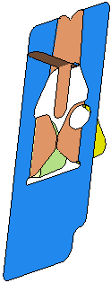
This is a toggle option - Remove Original Faces / Keep Original FacesRemove Original Faces / Keep Original Faces. When the default Remove Original Faces is selected, the original faces are removed, as shown here and in the results of the procedure below. When toggled Keep Original Faces is selected the original faces are maintained.
Remove Original Faces
Keep Original Faces
Region (Offset) of Influence
This controls if the local blank is limited to the selected faces only (if the value = 0.000) or if an area of the fixed face will participate in the local blank (to smoothen the result).
Examples of use:Examples of use:
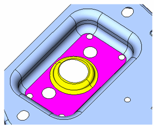
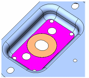
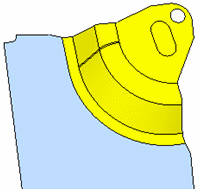
For example, in the picture below, the yellow faces should be locally blanked with respect to the fixed (blue) face:
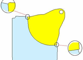
The result is not a smooth connection between the original (fixed) face and the newly created face:
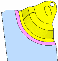
Using a region of influence will "use" the region closest to the fixed boundaries (the purple area in the picture below) as part of the Finite Element solution):
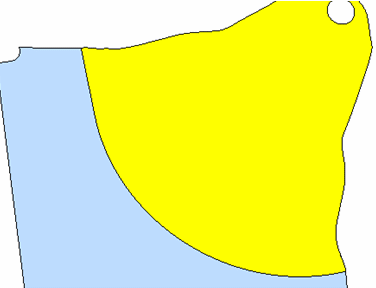
The result is much smoother:
Interaction examples:Interaction examples:
When the Region of Influence = 0, the local blank is limited to the selected faces only.
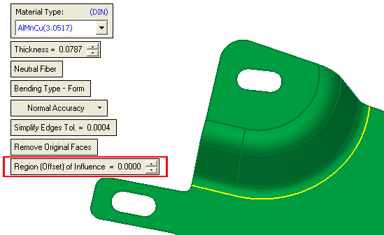
When the Region of Influence > 0, the offset amount within the fixed area is displayed.
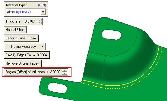
Notes: If required you can click the blue arrow to change the direction of the local blank operation.
-
ExitExit the step.
Optional Step 1 
- Define the transfer entities. For further details on defining transfer entities, see Additional Example, shown below.
Optional Step 2 
- Show the analysis results. This step is identical to the appropriate options in the Show Analysis function.

- Click OKOK or ApplyApply in the Feature Guide to complete the function.

When completed, the Local Blank feature will appear in the Feature Tree

Additional ExampleAdditional Example
Required Step 1  : Pick the Reference Face
Required Step 2  : Pick the Face(s) to Blank
-
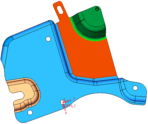
Pick the required face to blank (marked in red). The system automatically identifies (and selects) all the faces adjacent smooth faces and unselect the cup marked in green,
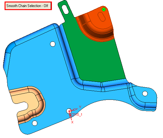
Note: Ensure the Smooth Chain Off option is selected
Required Step 3
parameters and <exit><exit> Selected Skin option is used.
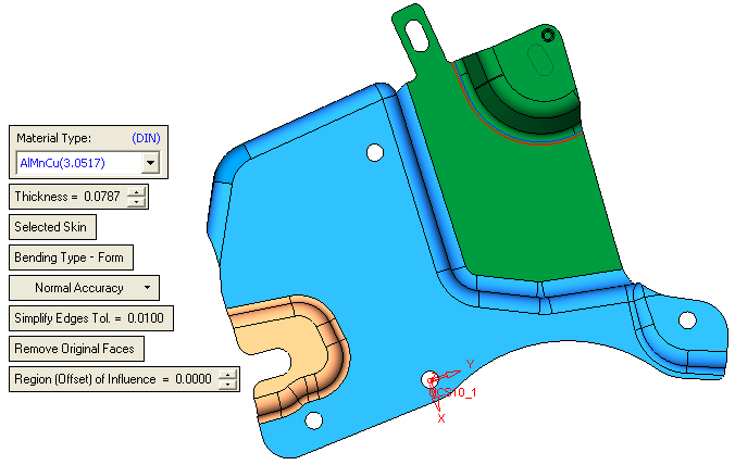
Optional Step 1  : Define Transfer Entities
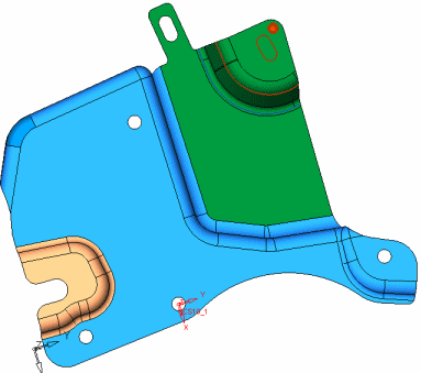
Pick the entities to be transferred (in the example below, marked in red),
Optional Step 2  : Show Analysis Results
This step is identical to the Show Analysis function.
Press OK ![]() or Apply
or Apply ![]() in the Feature Guide to complete the function,
in the Feature Guide to complete the function,
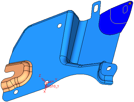
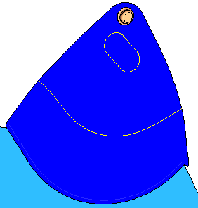
Note, that the cup has not been blanked due to the fact that it was unselected and therefore was not included in the blank operation, see additional enlargement of the area, in the picture below:
|


