|
|
Machining Method (Horiz. Machining Method)
Define the method for machining horizontal areas.
Note: The display of some of the Horiz. Machining Method options is dependent upon the current procedure:
|
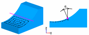
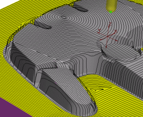
Spiral |
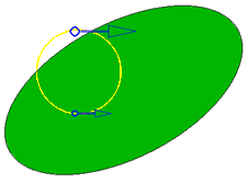
Machine the area using Spiral machining technology.
Additional Image:Additional Image:
|
||||
|
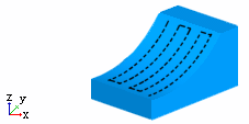
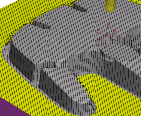
Parallel |
Machine the area using Parallel machining technology. When this option is selected, the parameter Horiz. Machining Order is displayed.
Additional Image:Additional Image:
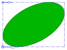
In the following procedures, when the Parallel machining method is selected, two arrows are displayed during the creation and editing stage of the procedure that represent the start point and direction of the milling; the large arrow signifies the machining start point and the small arrow signifies the machining end point:
To flip the machining start point, either click on the big arrow or press the Flip button (in the Flip Start Side parameter under Tool Trajectory - see the notes below). This swaps the machining start side (the big arrow [machining start point] becomes the small arrow [machining end point] and vice versa). The angle of these arrows are affected by the Milling at Angle parameter; if this parameter value is changed, the angle of the milling direction arrows also change. Notes:
|
||||
|
Layers |
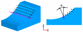
Machine vertical areas using Layers machining technology.
Additional Image:Additional Image:
Note: This option is displayed in Finish Mill All. When Layers technology is selected, the following checkbox parameter is displayed:
|
||||
|
Helical |
Machine the vertical areas using Helical motions. When Helical technology is selected, the following checkbox parameters are displayed:
|
||||
|
3D Step |
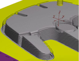
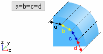
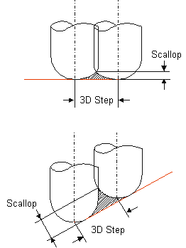
Machine the area using Spiral-like tool motions when the distance between the motions is a fixed 3D distance. 3D distance is the distance between two adjacent tool passes, measured between the tool tip point positions. This is useful when you have to mill horizontal and/or vertical surfaces in one milling operation.
Additional Image:Additional Image:
Note: This option is displayed in the following procedures:
|
||||
|
Parallel 5X Lead |
Machine the area using Parallel machining technology using a Preferred 5X Lead Angle.
In order to improve Surface quality it is better to touch the material with a point on the cutter that is as close as possible to its outer diameter, where the tangential velocity is at its highest. This can be achieved by giving the tool a Preferred 5X Lead Angle which will cause the touch point to move away from the tool center. In the case of Finish Parallel, the cutter is tilted forward in the direction of the parallel lines. In the picture below, the difference in surface quality can clearly be seen: - the furthest half was machined using 5X Lead - the closest half was machined using 3X.
To define the lead angle, the parameter Preferred 5X Lead Angle is displayed if the Parallel 5X Lead option is selected. When the Parallel 5X Lead option is selected, the parameter Horiz. Machining Order is displayed. Note: This option is displayed in Finish Mill All, Finish Mill by Limit Angle and Finish Horiz. Planar Areas, under the following conditions:
|
|
