|
|
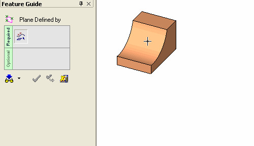
Plane Defined By 


Access: Invoke this function from one of the following locations:
-
Click the
button in the toolbar. -
Select Wireframe > Datum > Plane Defined By from the menu bar.
Create a plane that passes through selected entities.
|
Demo: Press the button below to view
a short movie demonstrating the function:
|
Practice: Press the button below to open Cimatron with a practice ELT file similar to that used to create the movie (if the relevant feature already exists in the ELT file, you can either edit it or delete it and create a new feature). |
|
|
|

General Interaction
The following is the Feature Guide for Plane Defined By.
|
|
|
Required Step 1 
Pick the references entities that define a plane. The following entities can be picked to create the plane:
|
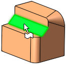
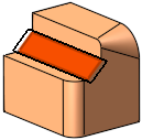
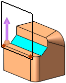
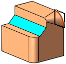
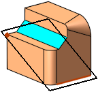
Planar face: |
Result: |
|
|
|
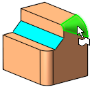
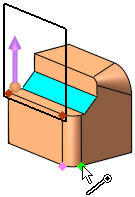
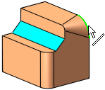
Non-planar faceNon-planar face
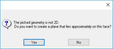
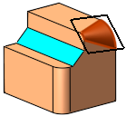
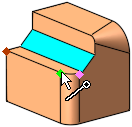
Picking a non-planar face produces an approximate plane which you can accept or cancel.
|
Non-planar face: |
Accept or cancel: |
Result: |
|
|
|
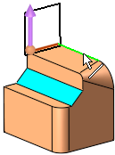
|
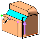
Upon picking the 2nd point to define the line, a plane is produced in the default direction of the Z plane which can then be changed by clicking the Directional Arrow. or picking a 3rd point.
|
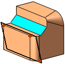
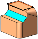
Planar face: |
Result: |
|
|
|
Note: In cases where the cross product between the Z direction of the active UCS and the line (or the vector from the 2 points) is smaller than 5 degrees, the default direction will be the X plane of the active UCS.
|
3 points: |
Result: |
|
|
|
2D curve / edge (non-linear)2D curve / edge (non-linear)
|
2D curve / edge: |
Result: |
|
|
|
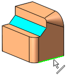
Line / linear edge / axisLine / linear edge / axis
|
Edge: |
Result: |
|
|
|
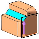
Line / linear edge / axis and a pointLine / linear edge / axis and a point
|
Edge and point: |
Result: |
|
|
|
2 intersecting lines2 intersecting lines
|
2 intersecting lines: |
Result: |
|
|
|
Notes:
-
When defining a plane for the Sketcher, the following Plane > Defined By methods are recognized by the Sketcher:
-
planar face
-
three points
-
line and a point
-
2D curve / edge (non-linear)
-
two intersecting lines
-
-
In certain cases, you can pick the entities and then enter the Plane Through function. If you do this, the selected entities will automatically be included in Step 1.
-
The default size of new main planes can be set by editing the Free Plane size relative to the Screen value in the General Preferences > Datum Planes.
When you are finished, press OK ![]() or Apply
or Apply ![]() in the Feature Guide to complete the function.
in the Feature Guide to complete the function.
The datum plane now appears, with drag handles for resizing.
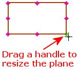
Note: The default size of plane drag handles can be set by editing the Plane Grab Handle size value in the General Preferences > Datum Planes.
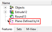
When completed, the Plane-Defined By feature will appear in the Feature Tree as follows:

|