|
|
Scale  /Shrinkage Compensation
  : Non-Uniform Scale: Options and Results


Access: Open this function from one of the following locations:
-
Select Solid > Objects > Scale from the menu bar.
-
Select Parting > Layout Tools > Shrink from the menu bar.
-
Select Parting Layout Tools > Shrink from the Mold Design Guide Toolbar or Parting Guide Toolbar.
|
Scale |
Scale geometry larger or smaller. |
|
Shrinkage Compensation |
Apply Shrinkage Compensation to compensate for part shrinkage during the mold material cooling process, after removal from the mold and cooling to room temperature. |
Scale or Shrinkage Compensate. These two functions are very similar; the main difference is that Scale can be performed multiple times, whereas Shrinkage Compensation is usually performed only once to compensate for part shrinkage during the cooling process.
In the Feature Tree, the Scale feature appears for both the Scale and Shrinkage Compensation functions, however they are separate features displaying different feature icons. This enables scaling and shrinkage compensation on the same part.
Scale operations may be performed multiple times, resulting in multiple Scale features.
Shrinkage Compensation is usually performed only once; any additional shrinkage compensation operation always updates the existing Shrinkage Compensation (Scale) feature (if one exists).
Enlarge or shrink geometry by a Non-Uniform scale factor (with a separate scale factor for each axis direction). Non-uniform scaling occurs when at least one of the scaling factors is different from the others and changes the shape of the geometry; e.g. a square may change into a rectangle, etc.
Note: For Scale and Shrinkage Compensation functions, Non-Uniform operations work with manual preview for performance issues, regardless of the defined preference options or if the automatic preview in the Feature Guide.
Note: Non-Uniform operations for Scale and Shrinkage Compensation functions will only work in manual preview mode for performance issues, regardless of the defined preference options or if automatic preview is set in the Feature Guide.
For more, see: The Automatic/Manual Preview Preference options.
Required Step 3 
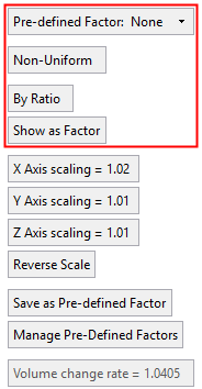
Set the Non-Uniform scale parameters. The following parameters are displayed:
|
None, By Ratio as Factor: |
None, |
None, By Bounding Box as Factor: |
||
|
|
|
|
|
|

Parameters
|
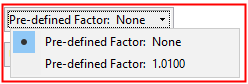
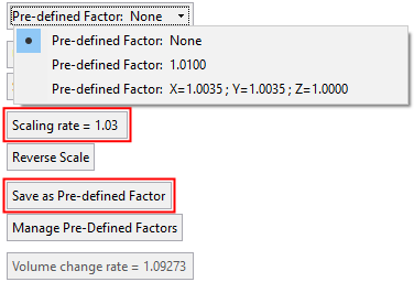
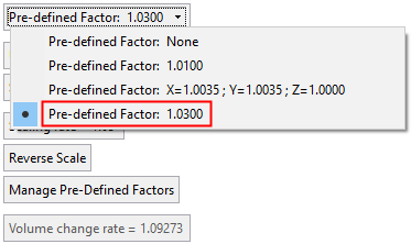
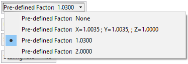
Pre-Defined Factor |
Select a scaling factor from the dropdown list. Either select a predefined scaling factor or select None to enter a new scaling amount. Parameter Examples:Parameter Examples:
The predefined scale factor list is saved in the ScaleFactors.xml file located in the following folder:
...\ProgramData\Cimatron\Cimatron\2026.0\Data The default predefined scaling factors are:
Uniform: 1.01. Non-Uniform: X = 1.01, Y = 1.01, Z = 1.01. Uniform: 1.0035. Non-Uniform: X = 1.0035, Y = 1.0035, Z = 1. |
||||||||||||||||
|
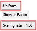
Uniform / |
This is a toggle option Uniform / Non-Uniform, enabling the selection of uniform or non-uniform scaling.
Parameter Examples:Parameter Examples:
|
||||||||||||||||
|
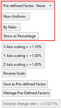
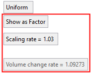
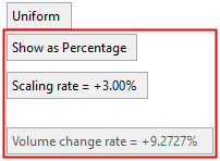
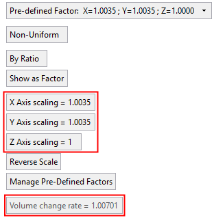
Volume Rate Change |
The total volume increase or decrease. This value is system calculated, based on the single scaling rate (for Uniform scaling) or the multi axis scaling rate (for Non-Uniform scaling). Parameter Examples:Parameter Examples:
|
||||||||||||||||
|
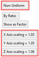
By Ratio / |
This is a toggle option By Ratio / By Bounding Box, to define the scaling method. This option is only displayed if Non-Uniform scaling is selected.
|
||||||||||||||||
|
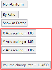
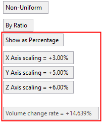
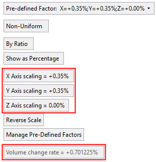
Show as Factor / |
This is a toggle option Show as Factor / Show as Percentage, enabling the scaling amount to be shown either as a factor (ratio) or as a percentage. Parameter Examples: Parameter Examples:
|
||||||||||||||||
|
Scaling |
Enter the scaling value(s). Either a single value for Uniform, or multiple axis values for Non-Uniform. Parameter Examples:Parameter Examples:
|
||||||||||||||||
|
Save as Pre-Defined Factor |
The Save as Pre-Defined Factor parameter is displayed if an entered scaling amount does not appear in the predefined list. Click this button to save the new scaling amount. When a scaling amount is saved as a predefined factor, it appears in the dropdown list. If material is assigned to the active part, the material data (the material name and any preset scaling factors assigned to that material) is added from the relevant material file to the list of predefined factors. Parameter Examples:Parameter Examples:
|
||||||||||||||||
|
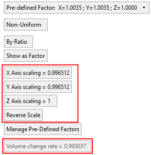
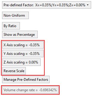
Reverse Scale |
This is a toggle button to reverse the scale (1/X) on the current value(s).
The resultant conversion value is displayed. Parameter Examples:Parameter Examples:
The Reverse Scale parameter only appears in the Scale function. |
||||||||||||||||
|
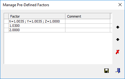
Manage Pre-Defined Factors |
Manage the list of predefined factors. The Manage Pre-Defined Factors dialog is displayed, showing the current content and order of the predefined factor list. This dialog enables you to perform the following operations on selected rows: change the order, add/edit a comment and delete. Save the changes.
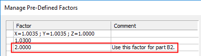
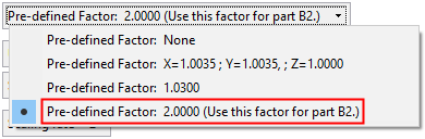
Add or edit a comment by double clicking the comment cell. The comment appears in parentheses adjacent to the factor in the dropdown.
Dialog Buttons:Dialog Buttons: Manage Pre-Defined Factors dialog buttons:
|
||||||||||||||||
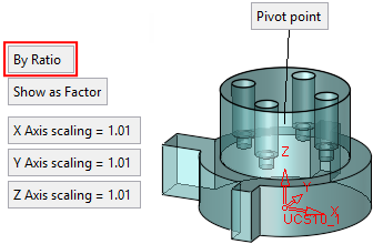
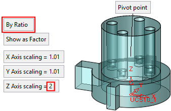
By Ratio
Create a non-uniform scale of entities by using the current boundaries. Enter a scaling factor for each axis.
|
The current scaling parameters are displayed. |
The dimensions are changed according to the changed axis direction. The total volume change is displayed. |
|
|
|
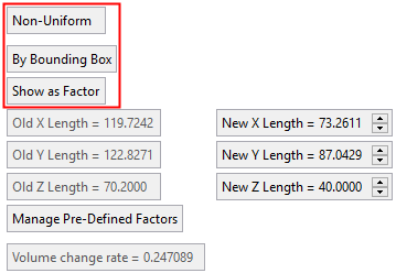
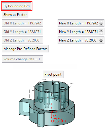
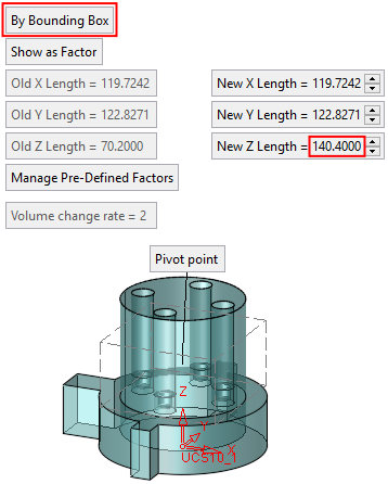
By Bounding Box
Create a non-uniform scale of entities by defining a new X, Y & Z bounding box length.
This option is not available if you chose the By Object option in the 1st step. The By Bounding Box option is only available if the input selection contains real geometry (objects, faces wire and not points or datums).
The system calculates the bounding box of the selected entities (before scaling) according to the active UCS and displays the box.
Two sets of parameters are displayed:
|
Old X/Y/Z Length |
These are the lengths of the bounding box - before scaling. These parameters are grayed out and are for display purposes only. |
|
New X/Y/Z Length |
These are the lengths of the bounding box - after scaling. These parameters can be edited to scale the entities. |
Set the New X/Y/Z Length Scale parameters. The new scaling is based on the selected pivot point.
|
The two sets of parameters are displayed. |
The dimensions are changed according to the changed axis direction. The total volume change is displayed. |
|
|
|
Click OKOK![]() or ApplyApply
or ApplyApply![]() in the Feature Guide to complete the function. The scaling is applied to the object.
in the Feature Guide to complete the function. The scaling is applied to the object.
To verify the results of the function, you can use the measuring tools to check the object dimensions.
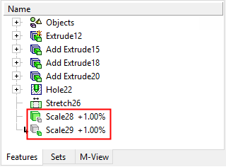
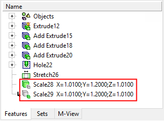
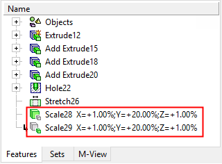
When completed, the Scale feature (together with the scaling data defined as a factor or a percentage) appears in the Feature Tree as follows:
|
Uniform - As Factor: |
Uniform - As Percentage: |
|
|
|
|
|
|
|
Non-Uniform - As Factor: |
Non-Uniform - As Percentage: |
|
|
|
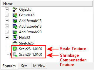
In the Feature Tree, the Scale feature appears for both the Scale and Shrinkage Compensation functions, however they are separate features displaying different feature icons. This enables scaling and shrinkage compensation on the same part.
Scale operations may be performed multiple times, resulting in multiple Scale features.
Shrinkage Compensation is usually performed only once; any additional shrinkage compensation operation always updates the existing Shrinkage Compensation (Scale) feature (if one exists).
Scale attribute: Cimatron Explorer - Preview & Properties, Advanced tab
A Scale attribute displays whether or not a scaling operation has been performed on the part.
The value of the Scale attribute is 1.0 if a scaling operation has not been performed. If the part has been scaled, the value of the last scale operation is displayed as shown below.

|