|
|
2.5 Axes
All 2.5-axis milling technologies based on 2D wireframe. These procedures can be used both as Volume Milling and Surface Milling for specific parts.
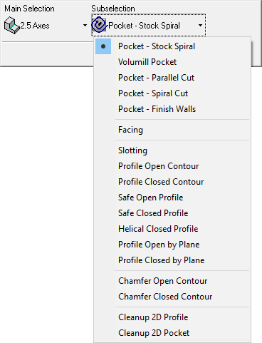
2.5 Axes Technologies
The following 2.5 Axes technologies are available in Cimatron:
|
2.5 Axis procedures |
Cut along the edges of open contours. |
|
|
Cut along the edges of open contours. |
||
|
Cut along the edges of open contours. |
||
|
Cut along the edges of open contours. |
||
|
Cut along the edges of open contours. |
||
|
Cut along the edges of open contours. |
||
|
Cut along the edges of open contours. |
||
|
Cut along the edges of open contours. |
||
|
Cut along the edges of open contours. |
||
|
Cut along the edges of open contours. |
||
|
Cut along the edges of open contours. |
||
|
Cut along the edges of open contours. |
||
|
Cut along the edges of open contours. |
||
|
Cut along the edge of closed contours, while following the shape of multiple part surfaces. |
||
|
Cut along the edges of open contours. |
||
|
Cut along the edges of open contours. |
||
|
Cut along the edges of open contours. |
||
|
Remove volume material from pocket features recognized by the Pocket Manager. |
||
Workflow
The workflow for NC Technologies consists of the following steps:
- Machine Definition. More:More:
This application enables you to construct a machine definition for the Machine Simulator. It enables defining the kinematics tree structure, the axes, and the displayed components of the CNC machine. This enables you to simulate the G-Code motions on a virtual machine that imitates the real machine behavior.
Important! This application is for use by qualified personnel only. Contact your Cimatron Provider or Reseller to get a machine definition for the Machine Simulator.
- NC Setup and Configuration. More:More:
The NC Setup enables you to predefine multiple project-related options in a single place. The NC Setup contains the general data associated with a project, such as the part material, part geometry, machining orientations, fixtures, initial stock, machine name, and post processor. The data defined in the NC Setup is later used as the default for various NC operations. For example, the defined part material is used to set different machining parameters in the cutter definition. The NC Setup parameters can be edited as required.
- Stock definition and update. More:More:
Stock is a 3X procedure used to represent the stock material from which the final part will be produced. Remaining stock is calculated after each procedure so that cutter motions can be optimized upon the current stock status. Stock is also used by the Simulator and Verifier. The remaining stock can be displayed at any time after any executed procedure (the procedure must have a  status flag).
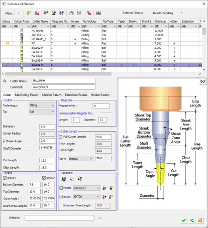
- Cutters and Holders definition. More:More:
Select a cutter for a procedure, define cutters and holders, and set machine and motion parameter defaults for specific cutters.
- Procedure selection. More:More:
Create a Procedure in the active toolpath. A Procedure is a set of cutter movements that conform to a specific machining technology. One or several Procedures can comprise a toolpath.
See Technologies, below.
- Geometry definition. More:More:
The Geometry Parameters define the geometrical entities to be used during the procedure operation.
- Review and output of the toolpath. More:More:
Once the toolpath is created and the procedure has been executed, perform operations on the toolpath to display and analyze the toolpath or edit cutter motions (Navigator, Global Filter, Motion Editor).
The Machining Simulation tools offer a combined environment for machining simulation that includes the following capabilities: material removal simulation, machine simulation, and verifier. These tools enable you to simulate and verify your NC toolpaths and procedures before implementing them on the shop floor.
- Report. More:More:
The NC Report is a file that provides various information about a set of selected procedures. This information includes details about the project and provider, as well as toolpaths, procedures (including multi-cutter information), and parameters.
A Cimatron Post Processor is a program that translates Cimatron NC (Numerical Control) data (toolpaths and procedures) into specific CNCCNC machine tool commands (machine code). These commands are known as Posts or G-Code programs (see the Glossary for additional information on G-Code).
Important: This application is for the use of qualified personnel only. Contact your Cimatron Provider or Reseller to create the appropriate G-Code.
|