|
|
Automated Drill: Define/Edit the Drilling Sequence
![]()
![]()
Access: Open this function from one of the following locations:
Select an Automated Drill procedure (from the Process Manager) and choose one of the following:
-
Select NC Utilities > Automated Drill > Define/Modify Sequence from the menu bar.
-
Select the appropriate group (see the note below) and then select NC Utilities > Automated Drill > Define/Modify Sequence from the menu bar.
-
Select the appropriate group (see the note below) and then select Define/Modify Sequence from the Automated Drill Guide.
-
Double-click the appropriate group (see the note below).
-
Right-click the appropriate Unassigned Group in the Group and Sequence Manager and select Define Sequence from the popup menu.
Note: The appropriate group can be either a Sequence Group or Unassigned Group.
Define/edit a Hole Sequence.
A Hole Sequence is a set of faces describing a hole.
This function enables you to pick a group of holes, define a technological process (drilling sequence) to machine the holes and attach the drilling sequence to the group.
Define or edit a drilling sequence for the selected group and attach the sequence to the group. The sequence definition is done by filling tables with the drill cutter order and parameters. These tables can either be filled manually from the Parameters table, or from the Cutter Table or from a sequence catalog.
In addition, you can also add Constraints (in the Geometrical Data area) and Conditions (in the Cutter Sequence Data area), where a particular process within a sequence can be activated according to the geometry of the specific Hole Group.
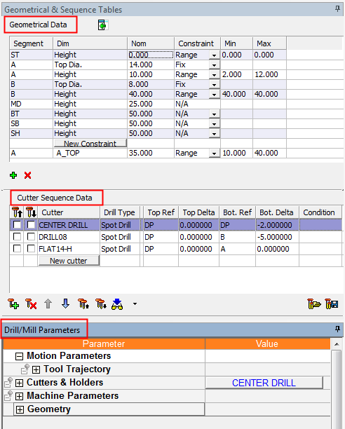
The following tables are used when creating a drilling sequence:
|
|
This table displays the geometrical data of the selected hole. Formula Expressions can also be used here - see below. |
|
|
This table displays some of the technological data required to drill the geometry in the Geometrical Data table. |
||
|
Drill/Mill Parameters - specifically the - Tool Trajectory Parameters |
This table displays the procedure-specific parameters, as is usual in Cimatron. However, the Motion Parameters / Tool Trajectory table, displays additional technological data required to drill the geometry in the Geometrical Data table. See here for Tool Trajectory parameter explanations. |
|