Enable 2D / 3D Cutter Compensation  /
/ 

Access: Open this function from one of the following locations:
-
When the procedure is closed, select NC-Utilities > Cutter Compensation from the menu bar. Select the required function.
Messages are displayed informing you that all relevant procedures will become suspended except for procedures with active 3D Cutter Compensation.
The options under NC-Utilities > Cutter Compensation are grayed out if 2D cutter compensation has never been activated in an NC file in Cimatron 10.0 and above.
-
In the Preferences > General NC. Select the required Cutter Compensation option from the dropdown list.
-
In the Machine Parameters Table of numerous procedures. Select the required Cutter Compensation option.
See Invoking Cutter Compensation and the List of Procedures below.
Cutter Compensation allows CNC operators to use a different cutter than the one used during the programming of a procedure. It enables the CNC machine controller, at run time, to compensate for any difference between the cutter currently being used by the machine and the cutter defined in the NC operation, and/or part offset, in order to achieve accuracy. This means that the machine controller calculates the correct offset from the surface to be cut based on the available cutters.
The advantage of this approach is that changes to the offset value are done directly on the machine without editing the NC code. This is useful when making changes to compensate for cutter wear, handling machining tolerances, or switching to a cutter with a different diameter.
Depending on the NC procedure, one or more of these options may be available.
Using cutter compensation enables accurate hole diameters, using any milling cutter.
One of the following cutter compensation parameters is displayed (cutter compensation can either be 2D or 3D):
|
Enable Cutter Compensation |
Enable 2D cutter compensation. The following G-Codes (or their equivalents) are used in 2D cutter compensation:
|
|
Enable 3D Cutter Compensation |
Enable 3D cutter compensation. The components of the direction of a 3 dimensional vector (I, J, K) are output at each cutter location. The machine can use these values to compensate for any difference between the cutter defined and the cutter currently being used, and/or part offset.
|
The Enable Cutter Compensation (2D/3D) parameter is displayed in the Machine Parameters Table.
- Parameters
- Detailed Parameter Explanations
- Invoking Geometry Location as Cutter Compensation
- List of Procedures (where each type of cutter compensation appears)
- Cutter Compensation and Post Processing Parameters
The following dropdown list options are available for the Enable Cutter Compensation (2D/3D) parameter (see Detailed Parameter Explanations for more detailed explanations with G-Code examples). In the explanations below, the following example part is used; a toolpath for this part has been programmed using the white contours as an input.
Parameters
The following cutter compensation options are available:
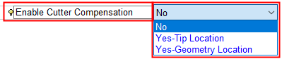
Depending on the NC procedure, one or more of these options may be available.
|
Do not use cutter compensation. See Detailed Parameter Explanations. |
|
|
|
Cutter tip location. Create the G-Code with an offset (equal to the cutter radius) to the user contours and compensate with the difference between the actual cutter radius and the programmed radius. In the example below, the toolpath "as tool tip location" (shown below in blue) will allow the shop floor to input the difference between the diameters of the current tool and the old tool at the machine.
|
|
|
Cutter geometry location. Create the G-Code on the user contours and compensate with the entire cutter radius. In the example below, the toolpath "as geometry" (shown below in blue) will allow the shop floor to simply input the diameter of the tool they are using. Note: In this example, in most areas the blue toolpath and the white input contours coincide. However, in the areas that were too small for the cutter, the toolpath is different than the input contours to prevent over machining.
When the Geometry Location option is selected, an additional parameter
is displayed in the Machine Parameters Table - Cutter
Compensation Additional Radius:
 This parameter appears only with "Geometry Location" and enables an extra margin to ensure that the controller will not reach a conflict if the real tool is exactly ø10 mm (R 5.0). By default, the Geometry Location method of cutter compensation initially does not appear in the dropdown list of cutter compensation options displayed in the Machine Parameters Table. See Detailed Parameter Explanations and Invoking Geometry Location as Cutter Compensation. |
Detailed parameter explanations
The following example is used to explain each of these options - milling on the right side of a straight line from X0, Y0 to X25, Y0, with a cutter of diameter 10 mm.
Sometimes the tool that was used to calculate the toolpath is not available on the shop floor. Or perhaps there is a desire to use a re-sharpened tool that has a slightly reduced diameter. Using the example above, we still want the cutting edge of the tool to mill along the line from X0, Y0 to X25, Y0. To do this the whole toolpath needs to be moved. Given the proper commands, the CNC machine controller can take the G-Code and offset the toolpath.
FANUC (and many other controllers) use the G40, G41 and G42 commands mentioned above. They work with values that are stored in the controller "D" registries in the same way as the length compensation works with the "H" registry.
No
Do not use cutter compensation.
In the milling example above, the tool tip moves from X0, Y-5 to X25, Y-5. The G-Code for this will look like this:
|
N40 G00 X0.0 Y-7. Z50. M09 |
[Move the tool tip in Rapid to X0 Y-7 Z+50] |
|
N50 Z1. |
[Move in Rapid to Z+1 - Plunge] |
|
N60 G01 Z0.0 F350 |
[Move in Feedrate (350) to Z0 - Plunge] |
|
N70 Y-5. |
[Move in Feedrate to Y-5 - Approach] |
|
N80 X25. |
[Move in Feedrate to X+25 - Milling] |
|
N90 Y-7. |
[Move in Feedrate to Y-7 - Retract] |
Tip location
Cutter tip location. Create the G-Code with an offset (equal to the cutter radius) to the user contours and compensate with the difference between the actual cutter radius and the programmed radius.
With this method, the machinist enters a correction value for the tool into the appropriate registry on the controller (ie: -0.1 for a re-sharpened ø10 mm tool that now has a radius of 4.9 mm).
In the milling example above, the G-Code for the same motion using Cutter Compensation - Tip Location would look the same up to N60:
|
N40 G00 X0.0 Y-7. Z50. M09 |
[Move the tool tip in Rapid to X0 Y-7 Z+50] |
|
N50 Z1. |
[Move in Rapid to Z+1 - Plunge] |
|
N60 G01 Z0.0 F350 |
[Move in Feedrate (350) to Z0 - Plunge] |
|
N70 G42 D51 Y-5. |
[Move in Feedrate to Y-5 – Approach, but compensate on the right side according to the value entered in Registry #51. If the milling (and approach/retract) were to be done on the left side of the line, the g-code would be G41] |
|
N80 X25. |
[Move in Feedrate to X+25 - Milling] |
|
N90 G40 Y-7. |
[Move in Feedrate to Y-7 – Retracting while cancelling the compensation] |
In Registry D51 on the machine controller, the operator must input the corrective value; ie. the NC program was created with a ø10 mm tool in mind. But if the real tool is ø9.8 mm, the value of 0.1 must be placed in Registry D51.
Geometry location
Cutter geometry location. Create the G-Code on the user contours and compensate with the entire cutter radius.
This method of Cutter Compensation uses the desired profile of the finished piece as the toolpath, and lets the machine controller calculate the real toolpath according to the real radius of the tool.
In the milling example above, (with the approach/retract on the left) the G-Code for the same motion using Cutter Compensation - Geometry Location would also look the same up to N60:
|
N40 G00 X0.0 Y2. Z50. M09 |
[Move in Rapid to X0 Y+2 Z+50] |
|
N50 Z1. |
[Move in Rapid to Z+1 - Plunge] |
|
N60 G01 Z0.0 F350 |
[Move in Feedrate (350) to Z0 - Plunge] |
|
N70 G41 D51 Y0.0 |
[Move in Feedrate to Y0 – Approach, but compensate on the left side according to the value entered in Registry #51] |
|
N80 X25. |
[Move in Feedrate to X+25 - Milling] |
|
N90 G40 Y2. |
[Move in Feedrate to Y+2 – Retracting while cancelling the compensation] |
Taking the example from above of a ø10 mm tool re-sharpened to ø9.8 mm, the value entered in Registry D51 would be the real radius of the tool: 4.9.
By default, the Geometry Location method of cutter compensation initially does not appear in the dropdown list cutter compensation options displayed in the Machine Parameters Table.
Invoking geometry location as cutter compensation
In the following example Geometry Location is selected as the Cutter Compensation method.
Selecting Geometry Location as the Cutter Compensation method
-
UseUse the required Cutter Compensation type.
-
When invoked from the NC Utilities menu, messages are displayed informing you that all relevant procedures will become suspended except for procedures with active 3D Cutter Compensation.
The options under NC-Utilities > Cutter Compensation are grayed out if 2D cutter compensation has never been activated in an NC file in Cimatron 10.0 and above. -
In the Preferences > GeneralNC, depending upon the current procedure type, change the Cutter Compensation - Milling Output option or the Cutter Compensation - Turning Output option to Geometry Location (from the dropdown list).
-
In the Machine Parameters Table, change the Enable Cutter Compensation to Yes-Geometry Location (from the dropdown list).
When the Geometry Location option is selected, an additional parameter
is displayed in the Machine Parameters Table - Cutter
Compensation Additional Radius:
This parameter appears only with "Geometry Location" and enables
an extra margin to ensure that the controller will not reach a conflict
if the real tool is exactly ø10 mm (R 5.0).
Notes:
-
When defining Geometry Location as the cutter compensation method, the NC-Utilities and Preferences stages (steps 1 and 2 above) are intentional. The results may be undesirable if the NC programmer and the machine operator are not synchronized about which Radius compensation method is being used.
-
If a discrepancy exists between the Cutter Compensation defined in the Preferences and that defined in the procedure, the procedure receives the system flag (*) indicating a discrepancy between data. This flag is displayed adjacent to the procedure in the Process Manager, for example:

In addition, when trying to Post Process or Machine Simulate a procedure with the * flag, a message is displayed that the G-Code cannot be created as the Cutter Compensation in at least one of the selected procedure(s) contradicts the type defined in the Preferences. -
If the cutter is changed, the Enable Cutter Compensation parameter in the Machine Parameters Table is changed to "No". This occurs whenever there is conflict between the Compensation type set in the procedure and the Preferences. Again, this is intentional to avoid mistakes.
-
When the Cutter Compensation is set to Geometry Location, the Show Toolpath by option is displayed in the Navigator:
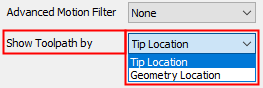
This option is only available when the procedure was executed using the Cutter Compensation: Yes-Geometry Location option. Normally, the Navigator shows the tool's motions according to the position of the tool tip.
When this option is changed to Geometry Location, the cutting edge of the tool is displayed, NOT the tool tip, or the coordinates that can be seen later in the G-Code after post processing.
List of procedures
The list of procedures where each type of cutter compensation appears, is shown below.
|
Main Selection |
Subselection |
Cutter Compensation Type |
|
2D |
||
|
3D |
||
|
2D |
||
|
3D |
||
|
3D |
||
|
3D |
||
|
2D |
||
Cutter compensation and post processing parameters
All compensated motions are linear. The post processor supports the cutter compensation vectors using SRF_NORX, SRF_NORY and SRF_NORZ as variables.
The touch point is available as parameters to the post using SRF_TOUCHY and SRF_TOUCHZ.
The post parameter COMP_3X (default = false) assumes true on approach, milling passes, retract and "On Surfaces" connections.