|
|
Runner Bodies  : Options and Results


Access: Open this function from one of the following locations:
-
Select Mold Design > Runner > Runner Bodies from the menu bar.
-
Select Runner Design > Runner Bodies from the Mold Design Guide Toolbar.
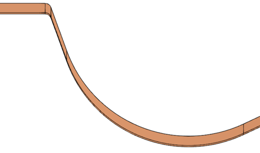
Create an object that defines the runner; this will be created around the runner contour.
This function creates the runner bodies around the sketched lines, contours, or 3D wire bodies (for 3D runners).
Important: Make sure that the required assembly is activated before using this operation.
Required Step 1 
Pick the wire entities (contours) to define the runner. Runner sketches, contours, or 3D wire bodies may be selected.
Press exitexit when finished.
Note: When creating 3D runners, the section of the runner is kept parallel to the Z axis (in order to avoid undercuts). This means that in steep angles the resulting runner will be shallow.
ExampleExample
Required Step 2 
Choose the type of cross-section for the runner.
The Runner Cross Section dialog is displayed.
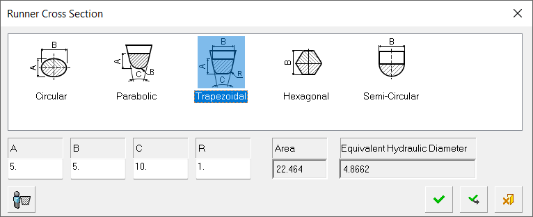
Choosing a cross-section
Either select the appropriate standard cross-section picture from the dialog, or press the Other Cross-Section button ![]() to define any 2D closed sketch from the display area. The default is the Trapezoidal cross-section, however, the last selected cross-section is kept.
to define any 2D closed sketch from the display area. The default is the Trapezoidal cross-section, however, the last selected cross-section is kept.
In the numeric fields, enter the desired size for each of the cross-section elements (A, B, C, R), according to the cross-section selected.
Based on the entered data, the Area and Equivalent Hydraulic Diameter are calculated; the latter is shown as EHD=4A/P (where "A" is the cross-sectional area and "P" is its perimeter length).
Press OK. The required cross-sectioncross-section is displayed, together with the following parameters:
|
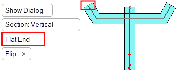
Flat End |
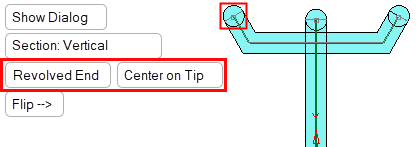
Revolved End |
|
|
|
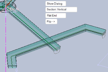
A direction arrow is displayed to set the cross-section direction of the runner. The direction arrow is based on the active UCS.
|
|
|
Set the parameters.
|
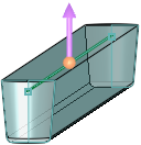
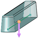
Flat End/ Revolved End |
Toggle option to select the type of ending for the runners (see the examples above).
|
||||||||||||||||
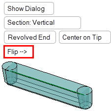
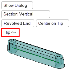
|
Flip |
Flip the cross-section direction.
|
||||||||||||||||
|
Section: Vertical / |
Toggle parameter to control Runner section orientation.
|
||||||||||||||||
|
Show Dialog |
Click this parameter to show or hide the Runner Cross Section dialog, which is used to change cross-section parameters. |
Optional Step 1 
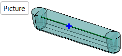
Adjust the local cross-sections of the segments. Blue crosses  are displayed on every segment.
Note: This optional step is only available when using one of the standard cross-sections displayed in the Required Step 2 It is not available when using the Other Cross-Section option.
Making local adjustments to cross-sections of specific segments
Pick the blue cross on the appropriate segment. The blue cross changes into a circle  and a dimension box is displayed, enabling you to make local changes to the dimensions of the cross-section.
Note: At this stage, the type of cross-section cannot be changed - only the local dimensions of the segment cross-section. To change the cross-section type, return to Required Step 2.
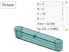
Change the local cross-section dimensions as required.
Click Picture to display a picture of the parameters currently being set. Close the picture by clicking the Close button ![]() .
.
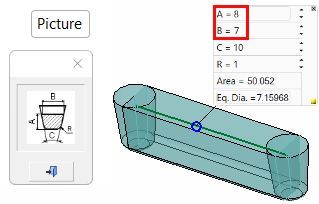
In the above example, parameters A and B have been changed. Note that, for each change, the following are recalculated and updated, the cross-section of the specific segment, the Area parameter and the Equivalent Hydraulic Diameter parameter (see above for the parameter explanations).
To Close individual dimension boxes, press the  button of the appropriate box. In this case, the local changes will be reset, the segment will return to its original dimensions and the blue cross will be re-displayed.
To Hide individual dimension boxes, press the ![]() button of the appropriate box. To re-show a hidden dimension box, pick the blue circle again.
button of the appropriate box. To re-show a hidden dimension box, pick the blue circle again.
Optional Step 2 
Set the Cold Slug Well parameters. At all runner intersections there should be a cold slug well; this is designed to trap the cooler advancing front of the molten mass, so enabling the hotter molten mass to reach the cavities.
The following parameters are displayed:
|
|
|
|

|
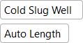
Cold Slug Well / |
This is a toggle option that enables you to either create the cold slug wells or to not create them. If None is selected, you are returned to the last required step. |
|
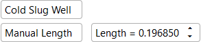
Auto Length / |
This is a toggle option that enables you to decide the length of the cold slug wells automatically or manually. If Manual Length is selected, a Length parameter is displayed to define the length manually. These lengths are 'global' lengths; each cold slug well can either be defined with this global length or with a specific 'local' length, see below. |
Cold Slug Wells can be created on "T intersections" and "Turn intersections" (any sharp corner including 3D); see the image below showing the cold slug wells in yellow.
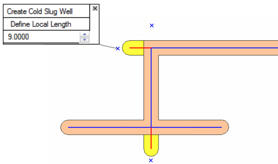
In case of a "T intersection", the extension direction is always along the middle leg. Note that the length of the extension is always to the tip of the well, and that it is always revolved, regardless of the definitions in the required steps.
In case of a "Turn intersection" there are 2 optional solutions. However, since the system doesn't know the direction of the flow, the longer leg is extended by default.
Next to each potential extension a blue X mark is displayed. Pick the X mark to display a dimension box enabling you to create a cold slug well and to either use the defined length or to make local changes to the length. The dimension box displays the following parameters:
|
Create Cold Slug Well / |
This is a toggle option that enables you to either create a cold slug well at this specific location or to not create it. |
||||
|
Use Defined Length / |
This is a toggle option:
|
||||
|
<Length> |
The third row shows the distance and spin box. When using Define Local Length, we will edit it. Changing back to Use Defined Length will change the value back to the automatic/general one. |
Notes:
-
Clicking an X next to a potential extension that does not have an extension will create one and open a dimension box for it. The default is set to Use Defined Length.
-
Clicking an X next to a potential extension that has an extension will open a dimension box for it. In this case, the last 2 rows of the dimension box are set by default to the same values as in the last opened dimension box. However, if it is the first opened dimension box, it will be set to Define Local Length and the 'global' value is initially displayed.
-
Clicking the small x on the dimension box changes the mode of that extension to Use Defined Length and closes the dimension box, but doesn’t remove the extension.
Press OK ![]() or Apply
or Apply ![]() in the Feature Guide to complete the function.
in the Feature Guide to complete the function.
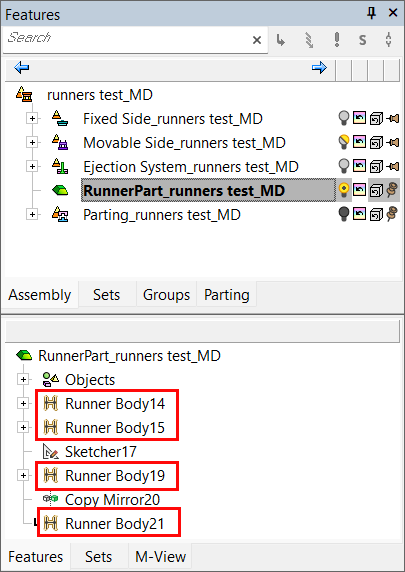
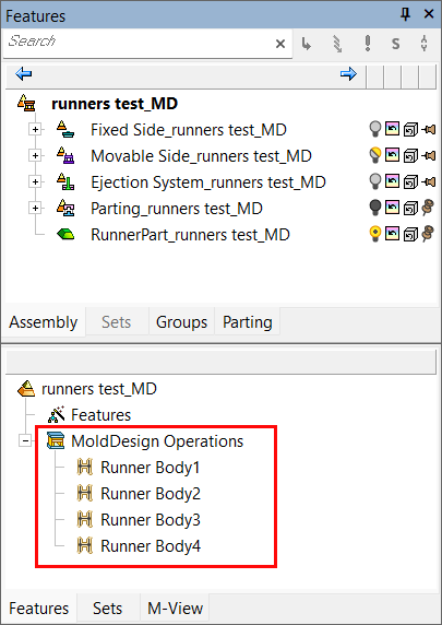
When completed, the Runner Body feature will appear in the relevant assembly and part Feature Trees.
|
|
|
|