|
CSV Points area
|
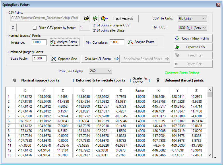
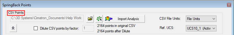
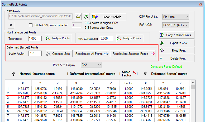
This area of the dialog enables you to load the CSV file containing the table of points and to set other parameters related to the points.
|

|
Browse to and load the CSV file containing the coordinates of the previously defined source and target points. The loaded data is displayed in the Springback Points dialog table.
The table area of the dialog displays the coordinates.
|
|

|
Pick an object with paired data. When this button is pressed, all objects with paired data are displayed with a texture.
Example:Example:
When these objects are selected, the paired data is loaded and displayed in the Springback Points dialog table. If the table already contains paired data, a confirmation message is displayed before replacing the existing data. The message has the following options:
Replace: Replace the existing paired data with the new paired data.
Add: Add the new paired data after the existing paired data.
This button is available if the Attach Pairs Data to Object option was selected in the Match Points on Skin function.
|
|
Import Analysis
|
Import a predefined springback analysis, instead of loading the CSV file. If an analysis does not exist, this button is dimmed. A springback analysis can be performed from the Show Analysis function.
The table area of the dialog displays the coordinates.
|
|
 / /
|
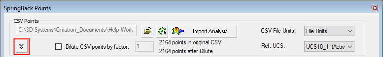
Toggle button to expand () or collapse () the dialog. In collapsed mode, the dialog only displays the CSV Points area.
Example:Example:
|
|
Dilute CSV points by factor
|
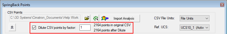
Reduce the number of source/target constraint points by the defined factor.
Select the checkbox to activate the factor value field. After changing the factor value, reload the CSV file to display the diluted points in the display area and the "number of points after the dilute" in the dialog.
Example:Example:
|
Dilute CSV points by factor = 1 or if the checkbox is not selected: all the source/target points are displayed.
|
Dilute CSV points by factor = 10; the display of the source/target points is diluted by the defined factor amount.
|
|
|
|
|
|
CSV File Units
|
Set the CSV file units from the dropdown list.
|
|
Ref. UCS
|
Set the reference UCS from the dropdown list of UCSs available in the part.
|
|
Create and Import Point Data
|
Create a Vector Data CSV file using the STL to CSV converter. Select the source (nominal) and target (deformed) data files, and use these to automatically populate the table.
|
|
|
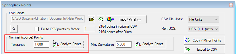
Nominal (source) Points area
|
This area of the dialog enables you to set the tolerance of, and to analyze, the defined source points. Points that do not lie on the input body within the defined tolerance, will be highlighted on the table.
|
Tolerance
|
Set the tolerance of the source points.
|
|
Analyze Points
|
Analyze the defined source points.
|
|
|
|
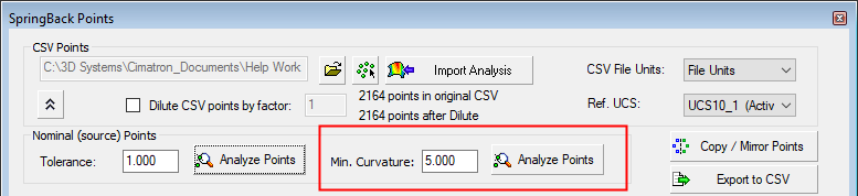
Detect points that lie on high curvature areas. Generally, for optimum system performance, areas of low curvature are preferred over those with high curvature. This option allows finding points that may be problematic. These points may then be deleted so that they are excluded from the operation.
|
Min. Curvature
|
Set the minimum curvature on which to detect points.
|
|
Analyze Points
|
Analyze the minimum curvature points.
|
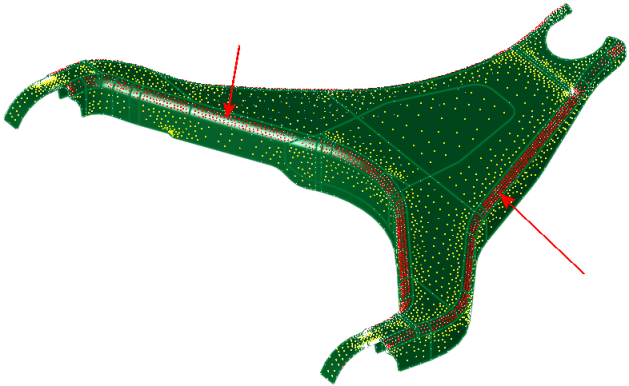
Example:Example:
Detected points lying on small curvatures:
|
|
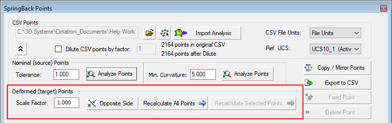
Deformed (target) Points area
|
This area of the dialog enables you to change the position of the target points (as defined in the previous steps of this function) and to calculate the Deformed (target) points, based on these changes.
|
Scale Factor
|
Set the scale factor of the target
points, where 1 is the same scale as the source points.
Example:Example:
|
Scale Factor = 1; the target points are located where they were originally positioned.
|
Scale Factor = 2; the target points are moved to a new position according to the scale factor.
|
|
|
|
|
|
Same Side
|
This is a toggle button that enables you to change the side of the target points from where they were originally positioned: Same Side / Opposite Side.
Example:Example:
|
Same Side: the target points are located where they were originally positioned.
|
Opposite Side: the target points are moved to the opposite side from where they were originally positioned.
|
|
|
|
|
|
Calculate/Recalulate All Points
|
Calculate the new target points for all the points in the table area of the dialog, based on the Scale Factor and Same Side / Opposite Side button. Once calculated, this button toggles to Recalculate All Points.
|
|
Recalulate Selected Points
|
Recalculate the new target points only for the point(s) selected in the table area of the dialog, based on the Scale Factor and Same Side / Opposite Side button.
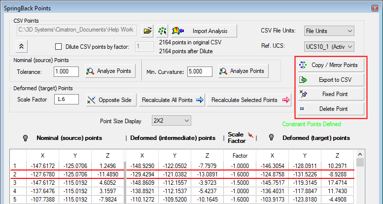
This option is only available when one (or more) rows of points are selected in the table area of the dialog. In the example below, multiple rows are selected. This enables the Scale Factor to be changed for all the selected rows and also for the selected rows to be recalculated.. Selected rows are highlighted.
Example:Example:
In the example below, multiple rows are selected. This enables the Scale Factor to be changed for all the selected rows and also for the selected rows to be recalculated.
|
|
|
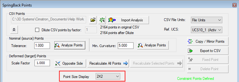
Point Size Display
|
Select the size of the displayed points from the adjacent dropdown list.
|
|
General area
|
This area of the dialog enables you to copy and mirror selected points, export point data to a CSV file, fix the location of a specific Nominal (source) and Deformed (intermediate) pair of points or to delete them. Multiple pairs of points can be selected for these operations.
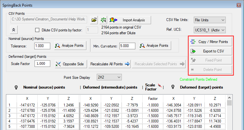
To select the required source/target pair of points, click the appropriate row number of the table of points; this highlights the row and activates the Fixed Point and Delete Point buttons (these buttons are dimmed until a row is selected).
To unselect a row, select anywhere on the table.
Example:Example:
|
Copy / Mirror Points
|
Copy (UCS to UCS) and mirror selected points from a point cloud.
See Springback Copy/Mirror Points.
|
|
Export to CSV
|
Export the point data to a CSV file.
|
|
Fixed Point
|
Fix the position of a source/target pair of points, irrespective of the settings of other parameters in this dialog.
|
|
Delete Point
|
Delete the selected source/target pair of points.
|
|
|
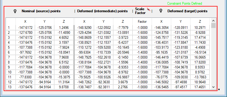
Table area
|
This area of the dialog displays the coordinates of the previously defined Nominal (source) and Deformed (intermediate) pair of points, the calculated Deformed (target) points, the Scale Factor and also enables you to hide/show the points on the part in the graphics area.
Single or multiple rows can be selected from the table. Select multiple rows using either the SHIFT or CTRL keys to select consecutive or non-consecutive rows respectively.
Hide/Show Examples:Hide/Show Examples:
|
Points not displayed:
( ) )
|
Source points displayed:
( ) )
|
|
|

|
Zoomed in:
|
Points not displayed:
()
|
Source points displayed:
()
|
Source and target points displayed:
()
|
|
|
|
|
|
Nominal (source) Points
|
The coordinates of the previously defined Nominal (source) points.
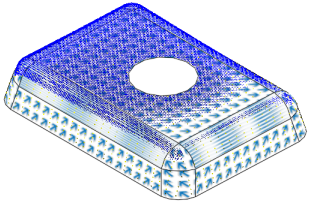
Use the hide/show toggle button (/) to hide or show the source points on the part.
|
|
Deformed (intermediate) Points
|
The coordinates of the previously defined target points. These points are shown as Deformed (intermediate) points; by setting additional options in this dialog, you can define these target points as final.
|
|
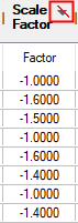
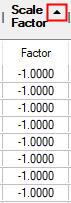
Scale Factor
|
Set the scale factor of the target
points, where 1 is the same scale as the source points.
In the example below, multiple rows are selected. This enables the Scale Factor to be changed for all the selected rows and also for the selected rows to be recalculated. Selected rows are highlighted.
Example:Example:
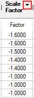
The table data can be sorted by the Scale Factor column. The icon in the column header is a 3 toggle option, indicating the sort status - None, Ascending and Descending.
Example:Example:
|
No Sorting:
|
Ascending:
|
Descending:
|
|
|
|
|
|
|
Deformed (target) Points
|
The coordinates of Deformed (target) points. These points are calculated based on the coordinates of the "intermediate" target points and the settings of the other parameters in this dialog.
Use the hide/show toggle button (/) to hide or show the final target points on the part.
|
|
 / Advanced Warping
  : Springback Points Dialog