|
|
Match Points on Skin  : Options and Results

Access: Open this function from one of the following locations:
Access: Open this function from the following location:
-
Select Die Design > Springback > Match Points on Skin from the menu bar.
-
Select Springback > Match Points on Skin from the following Die Design Guide: Die Process Design Guide (Forming).
-
Select Solid > Warp > Match Points on Skin from the menu bar.
To compensate for warpage, create pairs of vectors between a source body (a mesh, a point cloud or regular points) and their projection onto the skin of a target body (B-rep or mesh). The result is paired data between the source and target and can either be saved within the Cimatron file or saved in an external CSV file. This pairing can then be used for Springback Deform.
Required Step 1 
-
Pick the source body (a mesh, a point cloud or regular points) to be projected onto the target skin.
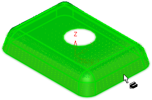
In this example, the source point cloud is shown below.
The source point cloud is selected.
- Click <exit><exit> to enter the next step.
Required Step 2 
-
Pick the target body, a skin body (B-rep or mesh) and define the pair creation method.
The parameters displayed depend on the source body (a mesh, a point cloud or regular points) selected in step 1.
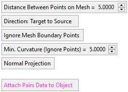
Parameters for a mesh object selected in step 1:
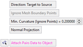
Parameters for a point cloud or points selected in step 1:
For each source point, the system finds a single point on the skin (the closest point) which is the NORMAL projection of the source point. A source point may have no projected point on the skin, as the vector between the original and resultant points must be normal to the skin. In addition, if there is more that one result of the projection, only the closest point (to the skin) is taken.
Distance Between Points on Mesh
Set the distance between the points on the mesh.
Default = 5mm (0.2 inch).This parameter is only displayed if a mesh object was selected in step 1.
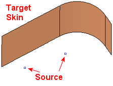
Direction: Target to Source / Direction: Source to Target
This is a toggle option Direction: Target to Source / Direction: Source to Target that enables you to select the projection direction for creating the pairs of vectors between the source body (selected in step 1) and the target skin body (selected in step 2). This influences the resultant CSV file where the first and second point depends on the option selected below. This option is not available when selecting a point cloud in step 1.
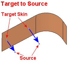
Target to Source
The pairing direction is from the target skin body to the source body. This is the default option.
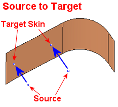
See the direction examples image below.Source to Target
The pairing direction is from the source body to the target skin body points projected onto the skin.
See the direction examples image below.Direction Examples:Direction Examples:
Ignore Mesh Boundary Points / Keep Points on Mesh Boundary
This is a toggle option Ignore Mesh Boundary Points / Keep Points on Mesh Boundary to either keep or ignore points on the mesh boundary.
Default = Ignore Mesh Boundary Points. This option is not available when selecting a point cloud in step 1.Min. Curvature (Ignore Points)
Set the minimum curvature of the skin for the creation of points. If the curvature anywhere in the skin is below the set minimum, points are not created on that section of the skin.
Example:Example: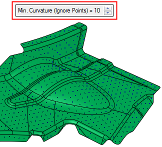

Normal Projection / Direction Projection
This is a toggle option Normal Projection / Direction Projection to select the projection direction between the source and target points to create the pairs of matching vectors.
Normal Projection
Projection normal to a selected body.
Pick a reference body to define the NORMAL projection of each source point to a target point. This is the default option.
The system finds the closest source points to the body and then a vector NORMAL to the adjacent face is used to find the matching target points (the closest point on the target point cloud (or STL) with respect to every source point).
Direction Projection
Select projection direction.
Select a direction to define the DIRECTION projection of each source point to a target point; the directional arrow is displayed. The default direction is Z of the active UCS.
The method for pairing the points is the same as for the Normal Projection, except that the direction is not normal but set by the DIRECTION vector.
If the Direction Projection option is selected, an additional toggle parameter One Side / Both Sides is displayed, enabling the projection on one or both sides of the source body (selected in step 1).
Save Pairs Data to CSV file / Attach Pairs Data to Object
This is a toggle option Save Pairs Data to CSV file / Attach Pairs Data to Object to save the pairs of matching vectors either in a CSV file or in the model itself. With either method, the pairing data can be loaded and displayed in the Springback table of points.
Save Pairs Data to CSV file
The resultant pairing between the source and target is saved in a CSV file.
Pick a skin object (B-rep or mesh) and click OK to create CSV pairs file.A Save As dialog is displayed; select the folder and file name to save the CSV file.
Attach Pairs Data to Object
The resultant pairing between the source and target is saved in the model.
Pick a skin object (B-rep or mesh) and define the pair creation method.
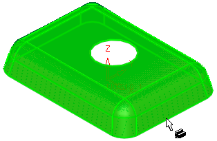
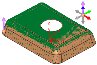
This is the default option.If this option is selected and a point cloud was selected in step 1, an adjacent icon
 prompts you to pick an object to which the paired data will be attached. An object must be selected for the function OK button to become available.
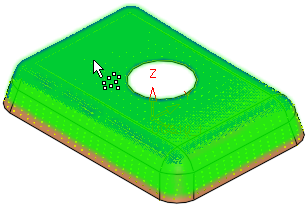
Once pair data is attached to an object and when this function or Springback Deform is opendopend, the object(s) with the linked data are displayed with a texture (to identify which objects have the linked data), as shown in the example below.
Example:Example: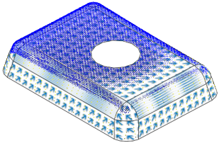
-
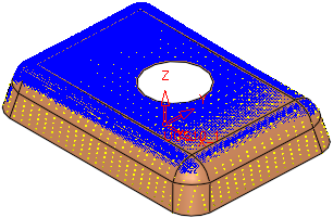
Click the Preview button on the Feature Guide to display a preview of the calculated point pairing, based on the selected projection method. All source points are displayed in purple and target points in blue, with a pairing line between appropriate pairs of points.
Example:Example:
-
Click OKOK
 or ApplyApply
 in the Feature Guide to complete the function.
- If the Save Pairs Data to CSV file toggle option was selected (the point pairing data is saved in a CSV file), the Save As dialog is displayed enabling you to save a CSV file of the pairs of matching vectors. The pairing data of these points can be loaded and displayed in the Springback table of points. The default save path for the CSV file is the path of the currently active file.
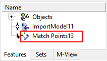
This does not create a feature in the Feature Tree, it only creates a CSV file of the point pairs. - If the Attach Pairs Data to Object toggle option was selected (the point pairing data is saved in the model itself), the Match Points feature is created in the Feature Tree. The pairing data of these points can be loaded and displayed in the Springback table of points.
The Feature Tree appears
- If the Save Pairs Data to CSV file toggle option was selected (the point pairing data is saved in a CSV file), the Save As dialog is displayed enabling you to save a CSV file of the pairs of matching vectors. The pairing data of these points can be loaded and displayed in the Springback table of points. The default save path for the CSV file is the path of the currently active file.
|