|
|
Turn to Reference: Reference Dimensions

Access: Invoke the Sketcher, define the sketch plane and then invoke this function from one of the following locations:
-
Click the Turn to Reference button
 in the Sketcher Dimension dialog.
 -
Click the Turn to Reference button
in the Sketcher toolbar.
This function appears in the Sketcher Dimension dialog and also in the Sketcher toolbar.
-
Access the Sketcher and then either:
-
While creating a dimension, press the Turn to Reference button
in the Sketcher
Dimension dialog.
-
Double-click an existing dimension (while in Select mode
 )
and press the Turn to Reference
button in the Sketcher
Dimension dialog.
)
and press the Turn to Reference
button in the Sketcher
Dimension dialog. -
Single-click a dimension or line (while in Select mode
)
and press the Turn to Reference
button in the Sketcher
toolbar.
-
Turn reference entities to geometry and vice versa.
Turn one or more regular sketcher entities (lines and/or dimensions) into reference entities and vice versa.
Extra dimensions you may want to define in a sketch can be made as Reference Dimensions. A Reference Dimension is not a constraint in the sketch; it is only used to show a resultant dimension from the geometry. For example, it can be used as a variable in a formula or show the distance between features.
A reference dimension does not influence the Sketcher but is derived from it. It is not possible to assign a specific value to a reference dimension, as long as it is defined as a reference dimension. Both inside the sketcher, and when showing sketcher parameters (by double-clicking an appropriate feature, editing parameters etc.), the reference dimension is shown with square parentheses and colored light green.
Every sketcher dimension, of every type, can be turned into a reference dimension and vice versa.
In the Sketcher, a reference dimension does not participate in any definition analysis; it is effectively non-existent in that sense. This is true also for geometric inconsistencies; a reference dimension cannot be the cause for geometric inconsistency.
A reference dimension can be used for creating parametric relations (i.e. other dimensions can be related to it). However, the reference dimension cannot be related to other parameters, nor can it be marked as a Leading Dimension.
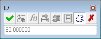
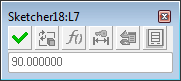
The Sketcher Dimension dialog for reference dimensions can be invoked normally (by double-clicking the reference dimension). In this case, the dialog shows the reference dimension with a grayed out background, meaning that it is disabled; options cannot be used and no value can be typed in. The only available buttons are OK (which closes the dialog), the Turn to Reference ![]() , and Delete (which deletes the dimension). All other buttons are grayed out and unavailable.
, and Delete (which deletes the dimension). All other buttons are grayed out and unavailable.
Just like regular sketcher dimensions, the reference dimensions can be exposed outside the Sketcher, i.e. they can be displayed just as any Sketcher parameter; they can be used in relations, etc.
Outside the Sketcher, when displaying the parameter dialog (Edit Parameters dialog) for a reference dimension, the dialog shows the reference dimension with a grayed out background, meaning that it is disabled; options cannot be used and no value can be typed in. The only available button is OK (which closes the dialog); all the other buttons are grayed out and unavailable.
A reference dimension cannot be used when creating catalog parts; the reference dimension cannot be selected to be added to the catalog table.
Working with reference dimensions
Additional Reference Dimension Examples
Independent Reference Dimensions
Combining reference lines and dimensions in the same operation
To work with reference dimensions:
Click the Select option ![]() from the Sketcher toolbar, or press <exit><exit> until you are in Select mode. The cursor changes to a black pointer
from the Sketcher toolbar, or press <exit><exit> until you are in Select mode. The cursor changes to a black pointer ![]() .
.
Click one or more dimensions whose status is to be changed (from regular to reference dimensions, or vice versa). All picked entities will change their status accordingly.
Reference and regular dimensions can be selected together. Regular dimensions will turn to reference dimensions and vice versa.
Lines and dimensions can be picked and modified together. Regular lines and dimensions will turn to reference lines and dimensions and vice versa.
Regarding dimensional constraints, turning a regular dimension into a reference dimension equates to deleting it, while turning a reference dimension into a regular dimension equates to adding a new dimensional constraint.
For example, the sketch below is seen as over-defined; click an appropriate dimension to change to a reference dimension.
Click the Turn to Reference tool ![]() .
.
The selected dimension is turned to a reference dimension and the sketch is fully defined.
Additional Reference Dimension Examples
Continuing with the above examples, if another dimension is turned into a reference dimension, the sketch will become under-defined.
|
This can be fixed by turning one reference dimension to a normal dimension: |
Or by adding an additional dimension, even if a similar reference dimension already exists: |
|
|
|
This is true when dealing with ALL constraints, not just dimensional constraints.
|
In the example below, the angle is over-defined, with both a "normal" constraint and also an angle definition: |
Once the regular angle dimension is turned into a reference dimension, the example is fully defined: |
|
|
|
|