|
|
Unbend Solid  : Options and Results
Access: Open this function from the following location:
Access: Open this function from one of the following locations:
-
Select Solid > Warp > Unbend Solid from the menu bar.
-
Select Die Design > Geometry Manipulation > Unbend Solid from the menu bar.
-
Select Geometry Manipulation > Unbend Solid from the following Die Design Guide: Die Process Design Guide (Forming).
Straighten bent solid objects.
Required Step 1 
Pick a reference (fixed) face (either planar or closed cylindrical) or press the curve filter to pick a straight edge.
Notes:
-
The cylindrical face must be closed (for example a pipe).
-
The planar face or straight edge must belong to a closed solid body.
-
The straight edge must be at the boundary of a cylindrical (or Cylindrical Nurb) face.
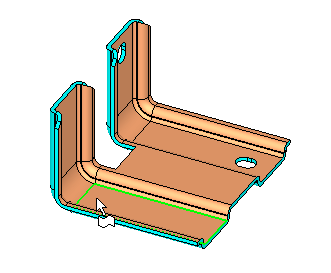
The system automatically selects a cylindrical face(s) that is adjacent to the selected entity (edge or planar face), if such a face exists. In the case of a planar face, all adjacent planar faces with the same normal are considered for selection.
The system then moves to the 2nd required step.
-
If you picked a planar face in the 1st required step, the picked point (on the face) helps to define the default selected cylindrical face.
-
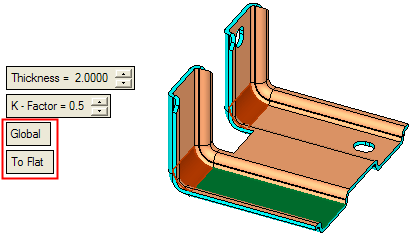
If you picked a planar face in the 1st required step, ALL planar faces (with the same normal) that are adjacent to this face will be taken into account by the system when selecting a cylindrical face(s). For example, in the case below, if you pick the green planar face, the system also considers the other blue faces when checking for a cylinder face(s). So, in this case, when you pick the green face, the system selects the purple cylindrical faces.
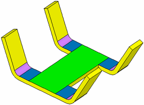
-
If you picked edge in the 1st required step and it belongs to single cylindrical face (if the other face is not cylindrical), the cylindrical face attached to this edge is automatically selected.
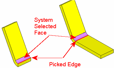
-
If you picked edge in the 1st required step and it belongs to 2 cylindrical faces, 1 of the faces is randomly selected.
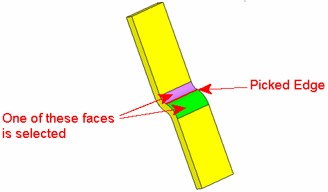
Required Step 2 
If required, unpick some of the system selected faces.
The following parameters are displayed (together with the system selected cylindrical faces):
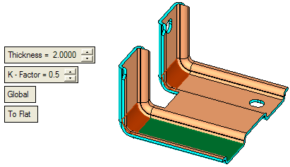
Set the parameters as required:
|
Thickness |
Enter the thickness of the object. For an explanation of this parameter, see the Bend function parameters. |
||||
|
K - Factor |
Enter the required K-Factor value. For an explanation of this parameter, see the Bend function parameters. |
||||
|
Global / Local |
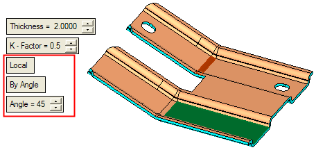
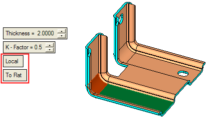
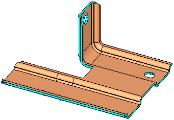
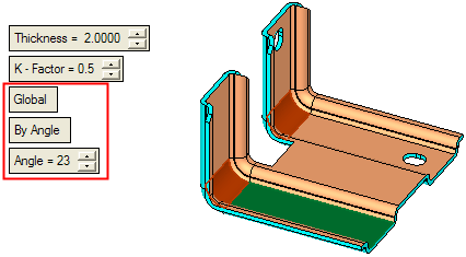
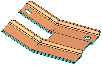
This is a toggle option: Global / Local:
|
||||
|
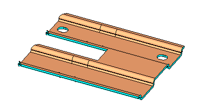
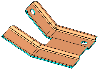
To Flat / By Angle |
This is a toggle option: To Flat / By Angle:
|
Click OK ![]() or Apply
or Apply ![]() in the Feature Guide to complete the function. The object is bent as per the defined parameters.
in the Feature Guide to complete the function. The object is bent as per the defined parameters.
When completed, the Unbend Solid feature will appear in the Feature Tree as follows:

|


