Mold Design

Adding Components

Applicative Add – Search & Favorites Picture 49

Within the Mold and Die menus are many types of Applicative Add functions. These provide specific functionality for placing tooling components (such as screws, plates, bolts, ejectors, and so on). For example, the parts are sorted via icon-based sub-categories and include smart sizing and positioning rules.

In Cimatron 2026, component selection has been enhanced by the addition of 2 new ways to more quickly find what you are looking for:

  1. Create a list of your most commonly used components.

    • The new Favorites tab will be empty at first. To create a favorite, just right click on the part while browsing by type and add it.

    • The favorites tab will only show those components that match the currently selected catalog.

    • To see a full list of every favorite, a new selection for All catalogs is available at the bottom of the catalog drop-down list.

    • You can remove a part from the Favorites tab by right-clicking it there and selecting Remove From Favorites.

  2. Search for a component by name.

    • The string search quickly scans an entire catalog folder for the keyword you want to find.

    • The last 5 keyword searches are kept for easy recall.

    • A search can be made of All Catalogs, but if there are thousands of parts this may take some time.

To find rarely used components, a catalog can now be searched by the part name.

Add a commonly used component to the favorites list
by using the right mouse button.

The favorites tab only shows your chosen components.
Removing a favorite is also a right mouse button click.

Parting and Binder creation

Extend & Cap Picture 53

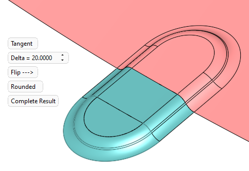
When designing the parting surface of a mold or the binder faces of a die, we often have to work hard to properly close off bumps, dips, or other changes in height that naturally occur along the perimeter of a part.

A new function in Cimatron 2026, called Extend and Cap, helps automate this process.

It combines the ability to extend the selected edges or part faces out into the shutoff region with a method of capping them off so that the shape is absorbed and the shutoff is simplified.

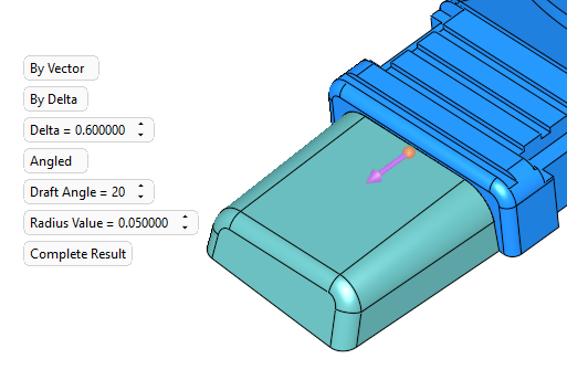
  • The extension from the part can be done in one of two ways - as a natural extension of the part shape or along a specified vector.

  • The capping off of the faces can be also be done one of two ways – by a flat and drafted face at a specified distance from the part, or by a full round-off of the shape.

Extend & Cap can be used on its own to help build the new parting or binder faces. However if the main parting or binder faces already exist, the function has an optional step that will extend and trim the new faces into the underlying geometry.

The construction methods used for mating the extended geometry to the underlying faces will be enhanced in the next version.

This contour along the parting line of a molded plastic part has been vector extended and then capped with a tapered face to provide a good shutoff condition.

This contour on the edge of a sheet metal stamping has been tangentially extended out into the binder area and then rounded off.

Cooling design

Improved access to Cooling object parameters  Picture 53

In Cimatron 2026 we’ve enhanced the accessibility to both the drill end extension parameters and to the type of mold cooling objects, by moving them into the main area of the function. This also allows their last used values to be remembered and reused.

  • The cooling object function does still have an optional step for drilled end control, but now this will only be used when a different style is needed for a specific endpoint.

In Cimatron 2025, only the channel diameter was a setting found in the main step of the Cooling Object function.

In Cimatron 2026, channel drilled ends data is stored as a global setting, meaning the last used value can be recalled.

New Cooling object preferences

The default values for cooling object parameters are now stored in Preferences.

A new page has been added under the MoldBase section called Cooling Object Holes where you may set all relevant parameters. The main channel line diameter is here, along with control over the drill type, extension, and bottom angle.

Like many preference pages, this new page can be set for MM or inch values, and be set as file specific or for the entire system.

An entirely new preference page was crated to hold the default values for Cooling objects.

Cooling Item with Channel – Drilled end control

The function to add a catalog cooling item with channel has many options, but control was lacking over the type of drilled end. Now this parameter, like all the others, retains its last used value.

In addition, selection of the drilled end type was added into the existing preference page for Cooling Item Holes.

Also added was a preference for the drill tip angle. This is not adjustable inside the function, so your desired value should be set here.

All channel parameters will remember
the values last used by the function.

Two new preferences help set a better default when adding Cooling items with channel.

Cooling items as the Same Component Picture 50

It’s always in the interest of design efficiency to utilize the Same Component option whenever possible. When adding Cooling items by channel, this is not often possible because by nature the depth of the channel varies at each location. Two depth options can however utilize Same Component.

  • Using the depth option ‘By Delta’ allows the use of same component, as the delta value is identical in each instance.

  • Using the depth option ‘No Channel’ allows the use of same component, as there is no channel at all in each instance.

Multiple cooling items can be added as the same component, if the channel option is not to create the channel.