|
Z-Top
|
Specify the Z value of the upper limit to be machined.
See also Z Values Source in the Tool Trajectory parameter grid.
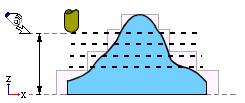
The first layer to be machined is usually at (Z-Top) - (Down Step).
The Z-Top may be defined differently according to the procedure within which it is used; see the Notes below.
Notes:
-
In the Rough, Finish Mill All (Layers) and Cleanup procedures, the first layer to be machined is at the defined Z-Top.
-
In the 2.5 Axes Chamfer procedure, this parameter is called Contour Z.
-
In 2.5 Axes Pocket and Profile procedures, when defining the contours of vertical walls, you select a single vertical wall or multiple walls manually or by criteria (e.g. color), and the system automatically identifies the contours and Z-Tops and Z-Bottoms.
Varying Z-Tops and Z-Bottoms can be applied according to the nature of each wall, and you can also select Z-Top Delta and Z-Bottom Delta so that the machining will start above or below the Z-Top and finish above or below the Z-Bottom if required. In addition, Reference Z Delta can also be defined.
The contour heights can be edited individually via the Contour Manager, or globally via the procedure parameter table.
The delta height values can be edited globally via the procedure parameter table.
-
In 2.5 Axes Slotting procedures,
|
|
Check Stock Above Z-Top
|
Check or don't check the stock (for unmachined areas) above the defined Z-Top.
 : If stock is detected above Z-Top, this area will not be machined (to avoid excessive chip load). In some cases, the safety factor used may "block" machining of certain regions (see the second note below). : If stock is detected above Z-Top, this area will not be machined (to avoid excessive chip load). In some cases, the safety factor used may "block" machining of certain regions (see the second note below).
 : If you are sure that there is no unmachined stock above Z-Top, unselect this parameter to receive better machining coverage. : If you are sure that there is no unmachined stock above Z-Top, unselect this parameter to receive better machining coverage.
|