Adding Geometry for Part / Assembly 

Access: Invoke the Sketcher, define the sketch plane and then invoke this function from the following location:
-
Click the Add Geometry button
in the Sketcher
toolbar.
The Add Geometry tool enables you to copy an entity from another plane or another sketch onto the current sketching plane.
Note: Using Add Geometry, the selected entities will be included as geometry in the sketch. If you want to add entities that will act only as a reference, and will not be included in the sketch, see Adding Reference Entities.
Copy a geometric entity from another plane and add it into the Sketcher plane
-
Select a plane. The selected plane is highlighted.
-
InvokeInvoke the Add Geometry function.
-
Pick geometry. The toggle option Project / Intersect is displayed enabling you to either project onto or intersect with the selected sketch plane. When selecting faces, make sure that the Face option is selected in the Selection Filter before picking the face.
-
If the Project option is selected, the selected geometry is copied and projected onto the sketch plane.
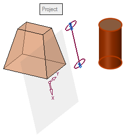
ExampleExampleCylindrical Faces Projection Example:
In the example below, a cylindrical face is selected. Note that entities that are not normal to the sketch plane can be selected (as seen below).
The result of this operation is that the selected geometry is copied onto the sketch plane. In this example, since the selected entity is a cylindrical face, the copied geometry is a line which is a projection of the cylinder axis and is the same length as the cylindrical face.
-
If the Intersect option is selected, the common geometry (between the selected geometry and the sketch plane) is highlighted. In the case of an intersection point (of the selected geometry with the sketch plane), the intersection point is highlighted.
ExampleExampleAny Geometry Intersect Example:
The geometry is selected. The intersection point of the geometry with the sketch plane is marked with a reference point. 
-
You can use the Undo function to cancel your selection.
-
When finished, press OK
 or Apply
  in the Feature Guide or on the Popup Submenu to complete the function. The Sketcher feature will appear in the Feature Tree.
Notes:
-
When adding Splines, the newly-created Spline is treated a "control points" Spline. This enables increased accuracy.
-
If you add a spline close to an arc or line, the spline is turned into an arc or line if it is within a predefined closeness tolerance level (currently 0.001 mm and 0.00004 inch). If it does not meet the tolerance level, then the spline remains as a spline.