Assembly Linear Array  :Options and Results


Access: Open this function from one of the following locations:
-
Click the
button in the
toolbar. -
Select Assembly > Copy > Assembly Linear Array from the menu bar.
Copy components in a linear array.
Create arrays of components in a linear pattern according to specified coordinates or UCS.
Required Step 1 
Pick the components to be copied.
|
|
|
The system moves to the next step.
Required Step 2 
- Select the coordinate system for the array either by picking a UCS or by picking points. If points are picked, the array is created based on a set of XY axes.
- The first point you select is the origin of the axes, the second point determines the X direction, and the third point sets the Y direction.
- The location of these points is not important, they are only used to set the relative copying directions from the selected entities.
-
Use MMB to <exit><exit> when the points are selected.
Required Step 3 
Set the parameters of the array. Note that direction arrows are displayed; click an arrow to flip the direction of the array axis.
|
Same Component |
Set the Same Component / Different Component switch options as appropriate. |
||||
|
Without Cut / With Cut |
Set the With Cut / Without Cut switch option as appropriate. If the With Cut option is selected, the Cut Manager is displayed in the optional step 2. |
||||
|
X Counter |
The total number of components in the X direction after copying, including the original. |
||||
|
X Delta |
Set the distance (spacing) between the copied components in the X direction. |
||||
|
Y Counter |
The total number of components in the Y direction after copying, including the original. |
||||
|
Y Delta |
Set the distance (spacing) between the copied components in the Y direction. |
||||
|
Full Array |
This switch option Full Array / Boundary is used to select how the entities are to be copied into the array.
|
Adjacent to each component instance in the array is a + symbol used to to turn the display of that instance ON or OFF.
- Click a + symbol to turn an instance OFF; the + is replaced with a O symbol.
- Clicking this O symbol re-displays the instance and the + symbol.
This provides control the number of instances within the array that you wish to display or work with.
An array must have at least one component instance; if you turn the last component instance OFF, the OK ![]() button in the Feature Guide is dimmed and is not available.
button in the Feature Guide is dimmed and is not available.
|
Click the + symbol to turn the instance off. |
Click the O symbol to re-display the instance. |
|
|
|
Optional Step 1 
Set the offset and rotation parameters for each instance in the array.
Adjacent to each component instance in the array is a + symbol that provides control the local offset and rotation parameters for that instance.
- Click a + symbol to display and set the offset and rotation parameters for that instance; the + is replaced with a O symbol.
- To cancel the offset and rotation settings for a component instance, click the X button on the top right corner of the parameter box.
- To hide the parameter box, click the yellow box at the bottom right corner of the parameter box; this is similar to the operation of the Dimension Box.
When dragging geometry along an axis, or rotating around an axis on screen, the Triad symbol is displayed.
Example:Example:
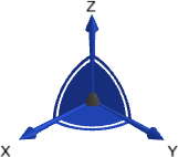
The Triad allows dragging in 3D, along the X, Y, and Z axes or on the XY, XZ and YZ planes (as well as free dragging). It also allows rotation dragging around each one of the axes (X axis, Y axis, or Z axis). The Triad Data Pane is displayed when dragging or rotating objects, providing real-time delta movement information.
|
Click the + symbol to display the local offset and rotation parameters. |
Set the parameters as required. |
|
|
|
Optional Step 2 
The Cut Manager is displayed if the With Cut option is selected in step 3; select the parts to be cut. This step provides manual control of which parts are to be cut.
Click OKOK![]() or ApplyApply
or ApplyApply![]() in the Feature Guide to complete the function.
in the Feature Guide to complete the function.
When completed, the Assembly Copy Array feature will appear in the Feature Tree as follows: