Modifying the BOM: By Table Editor

Access: Open this function from one of the following locations:
-
Click the
 button in the toolbar.
 -
Select Assembly > Main Tools > BOM from the menu bar.
-
Select BOM from the Mold Design Guide Toolbar.
Modify the BoM using the BOM Table Editor dialog buttons and Popup menu options.
To enter text in a column, double-click in the column.
For additional information see:
- Dialog Buttons
- Buttons Specific in the Assembly Environment
- BOM Table Editing Operations - Assembly
- BOM Report - Assembly
Dialog buttons
A similar dialog is displayed when editing the Assembly BOM Table, Drafting BOM Table and the Drafting Coordinate Table. The buttons below are common to each of these tables. Each of these tables has additional button(s) which are described in the relevant topic.
Buttons Common to All BOM Dialogs
|
|
Select Columns: Select which columns will appear in the table as well as their order, and create new columns. The properties of individual columns (such as name, width, and text justification - left, center, right) can also be defined. Note: Column widths can also be set dynamically from the BOM Table Editor dialog or from the BOM Table in the Drafting Sheet. In both these areas, drag the appropriate column walls to the required width. The Column Chooser dialog is displayed. |
||||
|
|
Add Row: Add rows to the table. |
||||
|
|
Sort BOM/Coordinate table: Sort the table according to field entries. The Sort TableSort Table dialog is displayed.
To sort the BOM fields:
The BOM is sorted appropriately. The BOM before sorting:The BOM before sorting:
The BOM after sorting:The BOM after sorting:
Press OK to update the BOM table in the Drafting Sheet.
|
||||
|
|
Renumber: Renumber the table entries, based on the current display, from 1 onwards. The difference between Renumber and Sort is that Renumber retains the current appearance, but just changes the numbering of the table entries. The examples below are for the BoM but are also relevant for the Coordinate Table. The BOM before renumbering:The BOM before renumbering:
The BOM after renumbering:The BOM after renumbering:
A Preference option blocks the reuse of ID numbers of deleted items. When selected, this means that only new ID numbers are assigned, instead of overwriting the ID numbers of deleted parts. |
||||
|
|
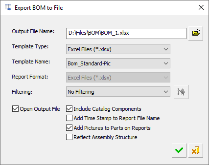
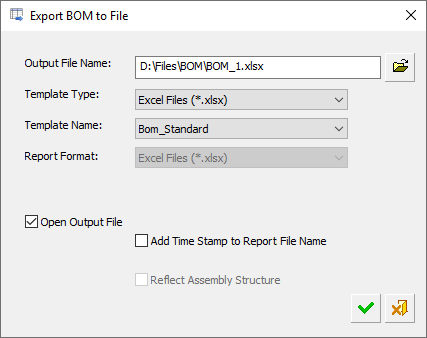
Export BOM to File/Coordinate table to file: In all cases, this displays the Export BOM to File dialog to save the relevant table as a file in the requested format. The Export BOM to File dialog differs slightly in the Assembly and Drafting environments. The Export BOM to File dialog is displayed.
See the BOM Report for additional information. |
||||
|
|
Save as BOM Template: Save the BoM template as an XML file. BTP File (*.btp) This file can then be retrieved (Set BoM Template - below), and used as a template for other BoMs. The Save as BOM TemplateSave as BOM Template Template dialog is displayed.
The BOM templates are saved as .btp files in the folder: |
||||
|
|
Set BOM Template: Retrieve a previously defined BoM template file (.btp) (Save as BoM Template - above), and use it for other BoMs. The Set BOM TemplateSet BOM Template dialog is displayed, select the required template.
The BoM templates are saved as .btp files in the folder: |
Buttons specific to the Assembly environment
In the Assembly environment, the following additional buttons are available in the Table Editor:
|
|
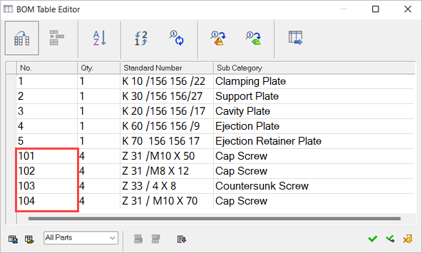
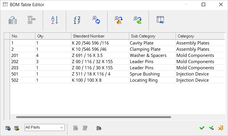
Recreate ID numbersThis recreates the ID numbers of the BOM after updating the idnum.dat file and/or the Short Type attribute of a file from the Cimatron Explorer. This button is dimmed unless the above-mentioned changes have occurred. Selecting Changes in the idnum.dat file (this can occur when the Assembly is open or closed). These changes can be: Changes to the number ranges. For example, the start number of "Screws & Bolts" has been changed from 101 to 150. Changes of the short type. For example, the "CPL" (Clamp Plate) from the "Assembly Plates" section has been moved to another location such as the "Screws & Bolts" section or any other section. Changes of the short type in the Cimatron Explorer (this can only occur when the assembly is closed). A dialog is displayed prompting you to confirm the request to recreate the ID numbers. Example: A BOM table showing the default ID numbers for "Screws & Bolts."
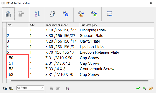
The same BOM table after the ID numbers have been recreated. In this example, the start number of "Screws & Bolts" has been changed from 101 to 150 in the idnum.dat file.
A Preference option blocks the reuse of ID numbers of deleted items. In this case, the Recreate ID numbers command ignores these ID numbers. |
||||||
|
|
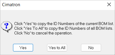
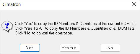
Copy ID numbers to all sub-assembliesThe Copy ID numbers & quantities to all parts propagates the ID numbers in the main Assembly BOM down to the relevant parts of the Sub-Assembly BOM, ensuring that the Sub-Assembly BOM's ID numbers are identical to those in the main Assembly BOM. When active, this function automatically assigns ID numbers and quantities to any new parts and propagates these changes to the lower Sub-Assemblies. In the case of a single unit Assembly, its components will receive numbers only if their siblings have numbers. This feature remains active until you manually turn it off (click the Note: Deactivating this function after it has been made switched on does NOT remove existing Part/Assembly file attributes (ID numbers and quantities). This dialog is displayed when you turn on the function.
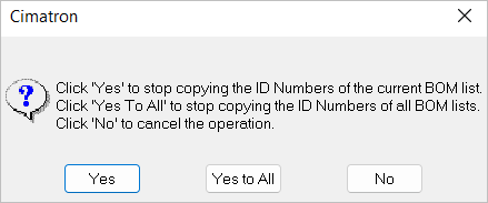
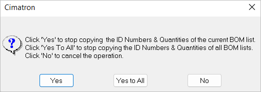
When deactivating this function, this dialog is displayed.
Example: The BOM table of the main Assembly Click the
The BOM table of the Movable Side of the Assembly before copying ID numbers to all Sub-Assemblies.
The BOM table of the Movable Side of the Assembly after copying ID numbers to all Sub-Assemblies. The ID numbers of the Sub-Assembly BOM are now the same as those of the main Assembly BOM. In this case, gaps may appear in the ID numbering.
|
||||||
|
|
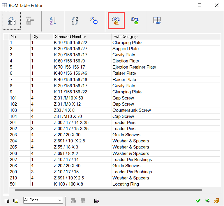
Copy ID numbers & quantities to all partsThis function propagates the ID numbers and quantities in the main Assembly BOM to each part, ensuring that parts' ID numbers and quantities will be identical to those in the main Assembly BOM. When active, this function automatically assigns ID numbers and quantities to new parts in the BOM and updates the part drawing to reflect these changes. In the case of a single unit Assembly, its components will get numbers only if their brothers have numbers. This function remains active until it is switched off (by clicking the Note: Deactivating this function after it has been made switched on does NOT remove existing part file attributes (ID numbers and quantities). When enabling this function, the following dialog is displayed, prompting you to select the appropriate option.
When disabling this function, the following dialog is displayed.
Example: The BOM table of the main Assembly Press
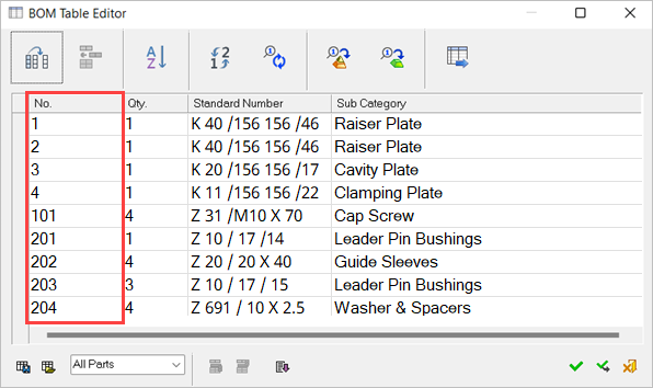
The ID numbers of parts in a part drawing are the same as those of the main Assembly BOM. In the example below, a view was created from part K20 and as soon as the ID number was connected to a Sub-Assembly (by picking one of the edges of the view or by pressing the Connect to Component button
|
||||||
|
|
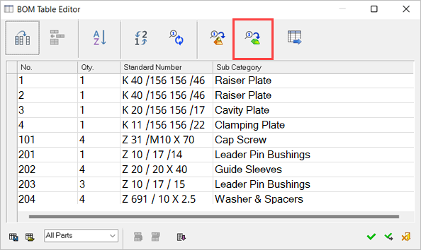
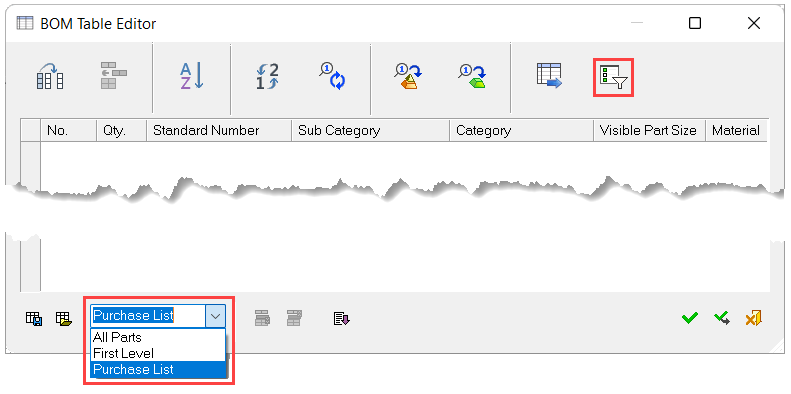
Sub-group purchase listThis option is displayed if the Purchase List option is selected when defining data (see below).
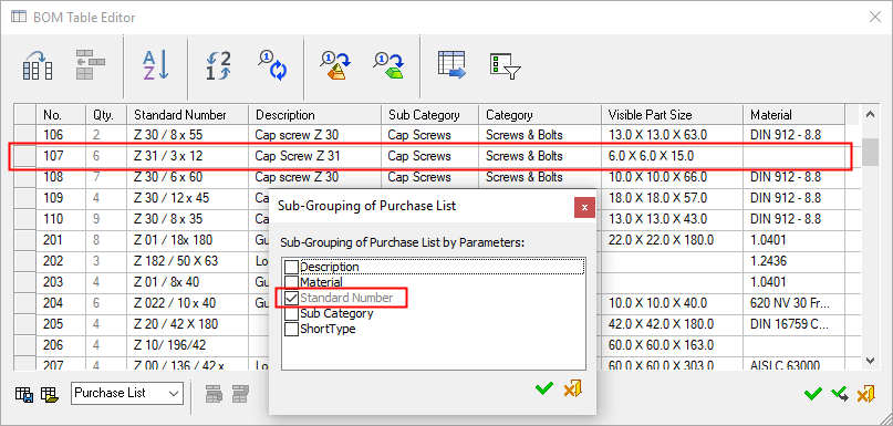
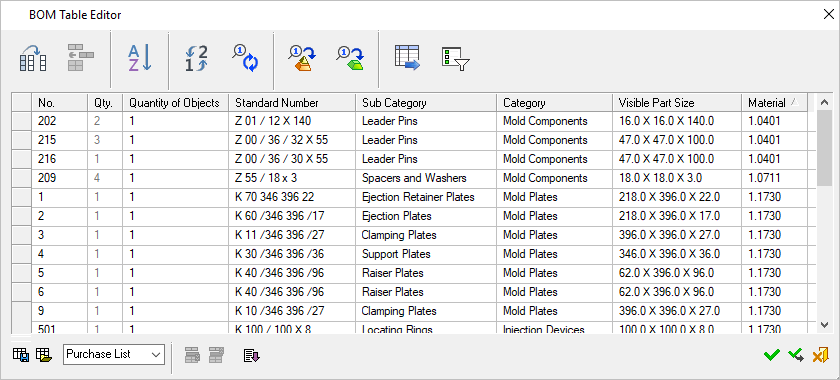
When creating a Purchase List BOM, the Sub-Group Purchase List option allows sub-grouping parameters based on additional criteria. For example, all parts with a specific standard number will appear by default as a single row, but may also be separated into different rows based on other criteria, such as their material or the supplier. The grouping parameter may be any BOM column.
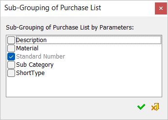
When the Group Purchase List option is clicked, the Sub-Grouping of Purchase List dialog is displayed.
This dialog contains a list with checkboxes of the BOM columns defined for the Sub-Group Purchase List in the BOM_Template.CSV file. The list of checkboxes in the dialog can be controlled in the Appear in Sub-Grouping List column in the BOM_Template.csv file. The default items on the list are shown in the dialog on the left. The Standard Number checkbox is ON Any checked attribute will be used to differentiate between items. For example, if 10 components have the same standard number they are represented as a single row in the BOM (in the purchase list). However, you may wish to add more parameters to the sub-grouping process. For example, if the Short Type attribute is added (checked ON
In the example below, the Standard Number column is checked ON
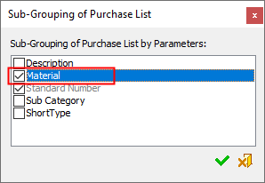
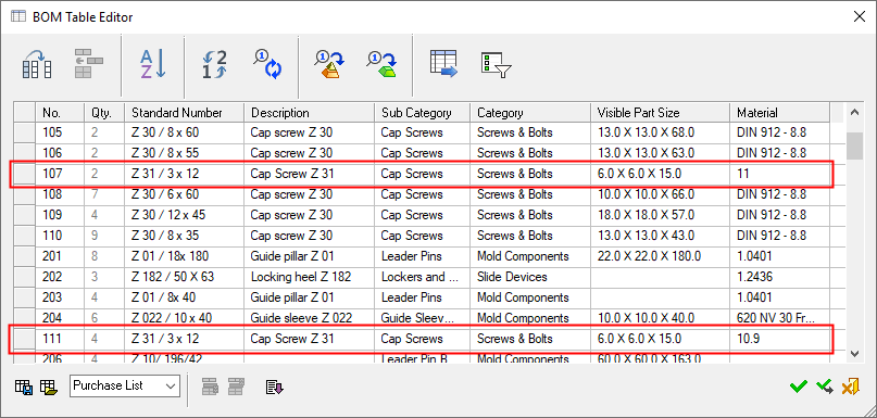
To modify the list to group all the screw parts with the same material in the same row in the Purchase List, switch ON
Note that now there are two different rows for the Z31 part, based on their different materials.
A configuration file determines which attributes
appear in the BOM file. System resource files are located under the folder: |
||||||
|
|
Define Data: Define which data will be included in the BOM and how it will be presented. The available options are:
For information on the Group Purchase List, see Dialog Buttons above. |
||||||
|
|
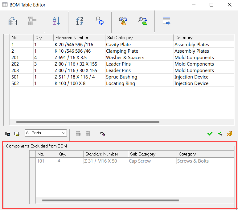
Exclude a part from the BOMThis button is only available for the All Parts option and if a part included in the BOM is selected.
|
||||||
|
|
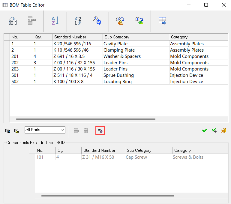
Include a part (that was previously excluded) in the BOMThis button is only available for the All Parts option and if a part excluded from the BOM is selected.
|
||||||
|
|
ExpandExpand the BOM Table Editor dialog to show the components excluded from the BOM window
Pressing the Expand button displays the additional window and also toggles the Expand button to the Collapse button |
||||||
|
|
CollapseCollapse the BOM Table Editor dialog to hide the components excluded from the BOM window
Pressing the Collapse button hides the additional window and also toggles the Collapse button to the Expand button |