|
|
Cimatron Explorer  : Properties > Advanced Tab

Access: Open this function from one of the following locations:
-
From the Cimatron Explorer: Select a file; the Preview & Properties pane is displayed by default. If the pane is not displayed, press the
button in the
Explorer toolbar. -
Select File > File Tools > Properties from the menu bar. This displays the properties for the main assembly.
-
Select Properties from any of the Assembly Tree popup submenus. This displays the properties for the selected component.
The Properties is the right-most pane of the Cimatron Explorer.
Explorer example:Explorer example:
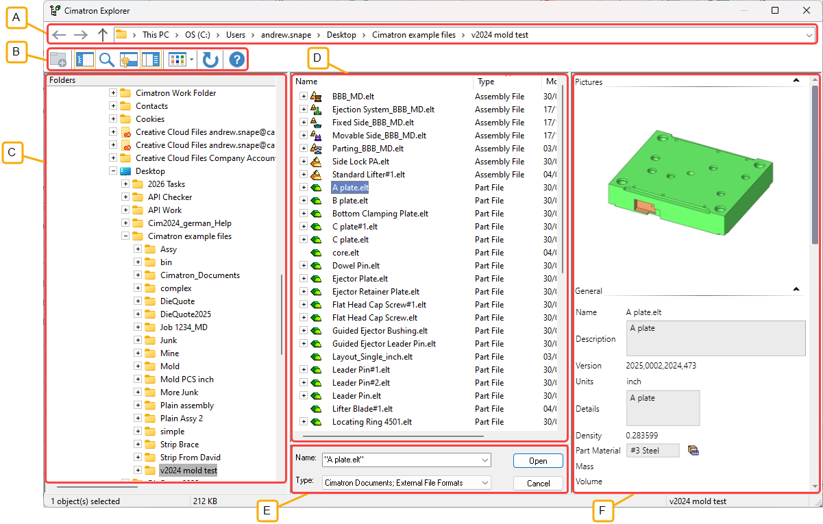
- Address Bar
- Toolbar
- Folder Tree
- File Control
- Command Control
- Properties
The Advanced tab of the Properties pane displays the Advanced file attributes.
System generated attributes are displayed in the right hand column of this tab. Attributes values on a gray background cannot be changed. If the file is not open, some of the attributes can be changed; these are displayed on a white background and can either be free text, selected from a dropdown menu, or a checkbox. However, once the file is opened, the file attributes are locked and cannot be changed from the Cimatron Explorer.
This user-entered information can be used as search criteria when running a query.
Advanced Tab Attributes
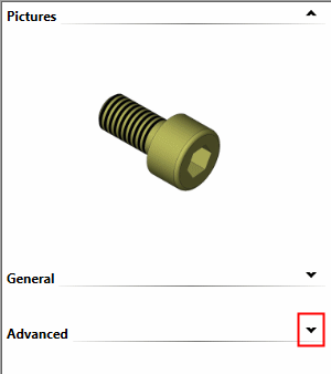
Display the Advanced attributes.
|
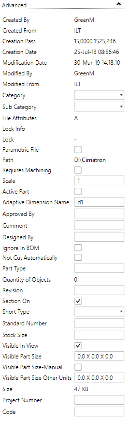
The Advanced attributes for an unopened file. The attributes within the white boxes can be changed. When a field is edited, the Changes Approval Options drop down from the top of the pane. |
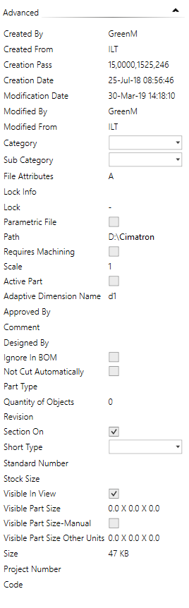
The Advanced attributes for an opened file. Attributes for open files cannot be changed from the Cimatron Explorer. |
|
|
|
|
Displaying an attribute in the Bill of Materials (BOM)
Adaptive Dimension Name - File Attribute Single Unit in BOM - File Attribute Sub-Assembly Type - File Attribute Catalog, Category and Sub-Category - File Attributes Ejector Lock Type - File Attribute Ignore in BOM - File Attribute Non-Standard Record (Catalog Part) - File Attribute Not Cut Automatically - File Attribute Parametric File - File Attribute Project Number - File Attribute Requires Machining - File Attribute Single Unit in BOM - File Attribute Standard Number - File Attribute Sub-Assembly Type - File Attribute |
Notes:
-
Attribute modifications that are done to a part using the Properties Pane of the Cimatron Explorer will be updated automatically within the Bill of Materials (BOM) when loading the Drafting file. The Standard Number attribute is an exception; see below.
-
It is highly recommended to modify all BOM-related attributes through the Bill of Materials (BOM) in the Assembly file.
Displaying an Attribute in the Bill of Materials (BOM)
To display an attribute in the Bill of Materials (BOM):
In the Cimatron Attributes Manager, select the required attribute and check the options in the Update Drafting Table section and also the Part and NC checkboxes in the Add Attribute To: section. Press OK to accept the changes and then press Save and Exit.
In the BOM Table Editor, open the Column Chooser and add the Visible Part Size column to the displayed columns in the BOM.
Adaptive Dimension Name - File Attribute
Add Catalog components with different diameters in a single operation by changing the diameter of the circles used to position them.
When using the Add Component > Place On Face option, you can control the diameter of added catalog parts by the diameter of circles you use in the Sketcher. This can be applied to any catalog part, but is mainly directed at ejectors and cooling parts (especially baffles).
The catalog part parameter, Adaptive Dimension Name, holds the name of the dimension that you wish to be used as the dimension that will fit the sketch diameter. For example, for a Hasco ejector, this parameter should have the value d1.
See Adaptive Diameter Control of Added Parts for additional information. This appears in the Add Component > Place on Face option when certain conditions are met.
Assembly - File Attributes
In the Assembly environment, specific attributes are displayed in the Advanced Tab.
|
Specific attributes: |
Sub-Assembly Type: |
|
|
|
In assemblies, the Standard Number and Short Type are the same as those for parts (see the notes above) but in this case, refer to the selected sub-assembly.
Single Unit in BOM - File Attribute
The Single Unit in BOM attribute enables you to show sub-assemblies that represent catalog items purchased as a single unit, as a single BOM row.
On the Bill of Materials, any small assembly of parts that can be ordered with a single part number can be defined as a Single Unit Sub-Assembly. This automatically removes the BOM rows for each of the individual pieces, and leaves a single row listing the assembly level catalog number. Single unit sub-assembly status can either be predefined on all of your standard components, or applied during compilation of the BOM to any assembly in the current design.
For additional information of the effects of using this attribute, see the BOM Notes related to BOM in the Assembly/MoldDesign environment.
Besides appearing in the Properties > Advanced tab pane of the Cimatron Explorer, this attribute can also be set within the option Single Unit SA (Sub-Assembly) in the Assembly Tree popup submenus.
Sub-Assembly Type - File Attribute
In the Assembly environment, the Sub-Assembly Type attribute is displayed that allows you to manually define sub-assemblies as either fixed, movable, or ejection sub-assemblies or, when selecting the Mold Assembly option, to mark the assembly as the main mold assembly.
The following dropdown options are available for this attribute:
|
|
This attribute is used when the sub-assembly was created in a mold set (using the Mold Project Setup Wizard) and is brought into another assembly (usually using the Add Duplicate function). This attribute will stay with the sub-assembly when it is moved between assemblies. This definition is important for different mold design tools and especially to ejector related tools. The default option is None. If the mold sets are created with the mold wizard, when the mold wizard is creating the mold sub-assemblies, it will attach the relevant attributes to them. Sub-assemblies that are manually defined as Sub-Assembly Type behave the same as mold sub-assemblies created internally by the system. |
Catalog, Category and Sub-Category - File Attributes
When a new catalog part is defined, the Catalog, Category and Sub-Category fields are empty. Using the dropdown menu for each field, define the appropriate catalog data.
Ejector Lock Type - File Attribute
An Ejector Lock Type attribute is assigned to each ejector after an Ejector Lock has been added. This attribute is used in the Table of Ejectors and the BOM Table.
Ignore in BOM - File Attribute
The Ignore in BOM checkbox is available for assemblies and parts.
When this checkbox is marked  , marked assemblies, including all of their children, are ignored in (excluded from) the Bill of Materials (BOM). Ignored assemblies/components appear in the Components Excluded from BOM list of the BOM Table Editor.
Selected assembly components can also be marked to be excluded or included in the BOM from the BOM Table Editor (for the All Parts option only):
-
Exclude from BOM
 - exclude a component from the BOM.
 -
Include in BOM
 - include a component (that was previously excluded) from the BOM.
Non-Standard Catalog Part / Stock Formula- File Attributes
If the part is a non standard catalog part , additional fields are displayed, as shown below:
|
Non Std Record: |
This file attribute, having the form of a record formula, is attached to the catalog part and is used if the part is made non-standard. For non-standard parts, this record formula, incorporating the real dimensions of the part, is then used as the Standard Number in the Cimatron Explorer, BOM, and the Assembly Tree. This field defines the Standard Number field using the usual record formula rules. For example, if the field is defined as <AAA_>P1< X >P2<_Non std> where P1 and P2 are primary dimensions and given the non-standard dimensions P1=13.2 and P2=17.6, then the resultant Standard Number will be AAA_13.2 X 17.6_Non std. This non-standard record number is then displayed as default when editing the parameters in the catalog table if a non-standard catalog part is the result (see an example heresee an example here).
If this field is empty, then the standard record is used. This means that if a part is made non-standard, the system uses the last valid standard record as the Standard Number. For example, when changing a standard 40X60 plate to the non-standard size 39.5X61, the string "40X60" would still appear everywhere (BOM, Assembly Tree, etc.). If this field has no parameters but just a string, then this string is used as the Standard Number. For example if the field entry is Non Std, then any non-standard part will have the Standard Number defined as Non Std. |
|
Stock Formula |
This file attribute, having the form of a record formula, is used to define the Stock Size for any catalog part (standard or not) in the Cimatron Explorer and BOM. This field defines the Stock Size field using the usual record formula rules. For example, if the field is P1< X >P2 where P1 and P2 are primary dimensions and given the non-standard dimensions P1=13.2 and P2=17.6, then the resultant Stock Size will be 13.2 X 17.6. If this field is empty, then the Stock Size field is left empty. If this field has no parameters but just a string, then this string is used as the Stock Size. |
Not Cut Automatically - File Attribute
Not Cut Automatically is an attribute that enables you to mark specific components (such as screws, nipples, plugs, etc.) that should not be cut by other components. This attribute is accessible from the Properties Pane of the Cimatron Explorer.
Parametric File - File Attribute
The Parametric File attribute can be used to mark files that have parametric data in them (namely - leading parameters and setup parameters). This attribute is user-controlled and is available for part, assembly, and NC files. When this attribute is ON (checkbox selected), a small icon is added to the file icon so that you can easily find them in the Cimatron Explorer; see the examples below.
|
Cimatron Explorer: |
Cimatron Explorer: |
Cimatron Explorer: |
|
|
|
|
Requires Machining - File Attribute
The Requires Machining attribute displays whether or not parts require machining. The default is OFF as shown in the image below.
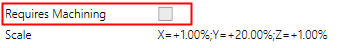
The Requires Machining attribute can be used when creating a Bill of Materials (BOM) in the Assembly and Drafting environments.
Scale - File Attribute
A Scale attribute displays whether or not a scaling operation has been performed on the part.
The value of the Scale attribute is 1.0 if a scaling operation has not been performed. If the part has been scaled, the value of the last scale operation is displayed as shown below.
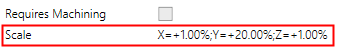
See Scale.
Short Type - File Attribute
The Short Type attribute can be selected from a dropdown list. The Short Type is the abbreviation for a component and is defined in the idnum.dat file (together with the component's full name and number). This information is used in the BOM.
|
|
Example Short Type dropdown list of options:
|
Standard Number - File Attribute
Attribute modifications that are done to a part using the Properties Pane of the Cimatron Explorer will be updated automatically within the Bill of Materials (BOM) when loading the Drafting file.
The Standard Number attribute is an exception, as this attribute affects the BOM topology (the number of rows in a Purchase List may change due to a change in this attribute). Therefore, if the Standard Number attribute was changed through the Cimatron Explorer, the Assembly file should be opened first in order to update the BOM in the drawing.
It is highly recommended to modify the Standard Number attribute (as well as other BOM-related attributes) through the Bill of Materials (BOM) in the Assembly file.
Stock Size - File Attribute
The Stock Size attribute value is displayed when the Save Stock Size as Attribute parameter in the Stock function is set.
Visible Part Size - File Attribute
The Visible Part Size attribute refers to the bounding box size of any part. Only the visible faces are included in the Visible Part Size attribute; curves are not included in the bounding box calculation. When activated (see below), the bounding box calculation is automatic and occurs while saving the part.
The Visible Part Size attribute can be used when creating a Bill of Materials (BOM) in the Assembly and Drafting environments and also as a Stock in Numerical Control (NC). The data of the bounding box of any part (also shown in the assembly) is automatically calculated when saving the part and placed in the Cimatron Explorer Properties pane for Modeling Parts and Numerical Control (NC) models. Assembly and Drafting files do not contain the Visible Part Size attribute.
The automatic recalculation of the part size while saving the part is activated from the Recalculate Part Size in Save Preference, where additional calculation criteria can be set.
Note: Rather than use the Stock function for each part, you can set the general preference for Recalculate Part Size in Save and let the system automatically measure part sizes at every save. Cimatron actually saves two automatic stock sizes for each part, one in the part units (Visible Part Size) and another in the alternate unit (Visible Part Size-Other Units).
In addition, checking the option for Visible Part Size – Manual allows you to manually type in a value for the Visible Part Size attribute; this value will not be overwritten when the part is saved again. This is very useful for standard parts or any time you want a specific size called out in the Bill of Materials.
Example:Example:
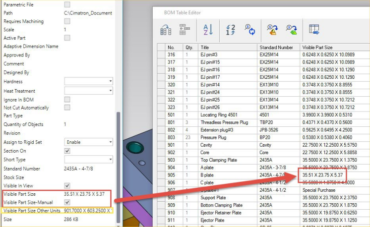
The following attributes are displayed:
If the Visible Part Size-Manual attribute is OFF (not selected), this means that the part size will be recalculated at every save operation.
If you wish to set a value for a specific part that will not be overwritten in the next Save operation, you can enter the Visible Part Size attribute values manually. To do this:
-
Open the Cimatron Explorer when the assembly or part is closed and display the following attributes:
-
Select the Visible Part Size-Manual checkbox, edit the displayed bounding box size, and save the changes.
-
Open the part and display the following attributes in the Cimatron Explorer. Notice that the value for the Visible Part Size-Manual attribute has changed from OFF to ON. This means that even if you change the actual visible sizes of the part, the values remain as specified.
Visible Part Size-Other Units - File Attribute
The Visible Part Size-Other Units attribute shows the visible part size in units that are opposite to those that are used in the file.
The Visible Part Size-Other Units attribute can be used when creating a Bill of Materials (BOM) in the Assembly and Drafting environments.
|