|
|
Blend : Options and Results


Access: Open this function from one of the following locations:
-
Click
in the toolbar. -
Select Faces > Main Tools > Blend from the menu bar.
-
Select Parting Surfaces > Blend from the Mold Design Guide Toolbar or Parting Guide Toolbar.
-
Select Blend on the popup menu if one or more edges, curves, composites, or sketches are selected.
Create a face by blending (connecting) between edges, sketches, contours, curves, and points.
General Interaction
Each entity picked (edge, curve, contour or point) is assigned a serial number. This number appears close to the pick location. All blend surfaces created or changed are immediately previewed on the screen. Any entity can be unpicked causing the serial number to update automatically. Alternatively, you can change the serial number by entering a new value which will in turn renumber the blended sections accordingly. ExampleExample
To enter section No. 6 before section 5, change the desired section (original No. 6) to 5. All the serial numbers will immediately update. Entering a value that is 1 or less sets the section as the first section. Entering a value that is greater than the last will set the section as the last one.
Required Step 1

-
PickPick two or more edges, sketches, composites, curves, or a point to define the blend sections. Re-pick any edge to unselect it.
The following parameters are displayed, depending on the number of edges selected.
|
2 edges selected |
|
> 2 edges selected |
|
|
|
-
Note than when picking the 3rd edge, the Open / Close toggle option appears. Selecting Close creates a closed Solid body. In this case the 1st and last edge slopes can be set to Free or Constant during Optional Step 1.
ExamplesExamples
|
1st edge selected |
2nd edge selected |
|
|
|
-
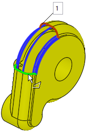
If required, toggle Single Face to Multi Faces to create a number of faces.
|
Single face |
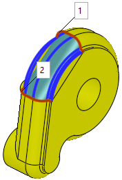
Multi faces |
|
|
|
Toggle the Single Face / Multi Faces button to create a single or multi faced feature, respectively. The resulting face geometry for the Multi Faces option generally produces higher quality results.
|
|
|
|
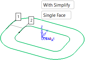
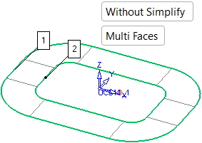
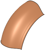
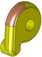
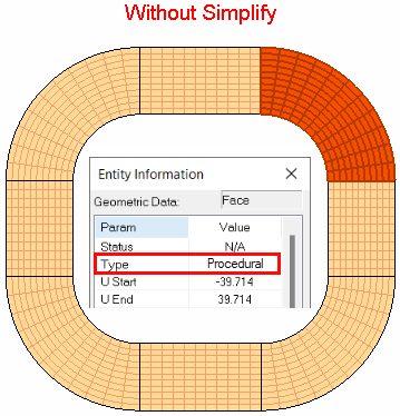
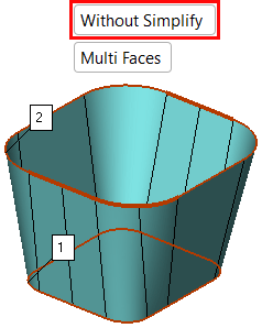
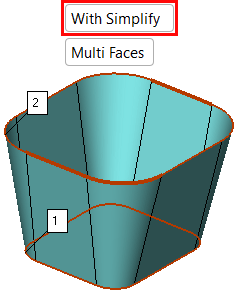
The Without Simplify / With Simplify toggle option lets you define the type of face to be created. Without Simplify produces a procedural type face while With Simplify approximates the procedural faces to analytic faces (planar, cone, etc.) and if this cannot be achieved, it approximates it to a NURB surface. This enables the surface to be machined using the Local Operations machining technology.
ExamplesExamples
| In the examples below, part of the Entity Information dialog is displayed to show the type of face produced. | |
|
Without Simplify |
With Simplify |
|
|
|

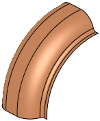
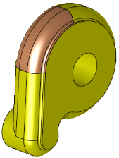
In addition, when using the With Simplify option, segmented edges of the same type are merged thereby producing fewer faces (the faces are based on the merged segmented edges).
ExamplesExamples
|
Segmented edges |
Without Simplify |
With Simplify |
|
|
|
|
-
ExitExit when all sections are selected. If this is the final result, press OK
 in the Feature Guide to complete the function.
Optional Step 1 
If you want to define slopes at the edges, see Defining Slopes.
Optional Step 2 
If you want to define boundaries for the face, see Defining Boundaries.
Click OKOK![]() or ApplyApply
or ApplyApply![]() in the Feature Guide to complete the function.
in the Feature Guide to complete the function.
When completed, the Blend feature will appear in the Feature Tree.

|