Copy Along Curve 


Access: Open this function from the following location:
Copy geometry along a curve.
Any type of entity can be copied and the target curve can either be 2D or 3D. A constraint plane can also be defined (to set the Z direction on a point on the curve).
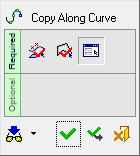
The following is the Feature Guide for Copy Along Curve.
|
|
 Tip: You can open the Feature Guide at any time by right-clicking the mouse in the graphic display area. Tip: You can open the Feature Guide at any time by right-clicking the mouse in the graphic display area.
|
Required Step 1 
Pick the reference entities to be copied. All types of entities can be picked. The cursor will tell you what you are picking, and you can use the Selection Filter to enable you to pick the entities you want.
If you pick a face and use Include the entire feature, all faces belonging to the same feature (created by the same function) will be automatically selected. Toggle Include the entire feature to Only picked faces if you want to pick individual faces. This toggle option will not appear if you select objects, curves, sketches, or faces of different features.
Press <exit><exit>(middle mouse button) when the required entities are picked.
Required Step 2 
Pick a curve or contour along which copies of the reference entity (selected in step 1) are to be positioned.
Press <exit><exit>(middle mouse button) when the required entities are picked.
Required Step 3 
Pick the reference UCS or point on the entity to be copied. This is the location point for the entity being copied.
When copying several faces from the
same body, the faces are not unstitched, but keep the original topology.
This does not apply if the Merge On
option is used (when available).
When you enter this step, the parameters shown below are displayed. When you pick the reference UCS or point, the copies of the entity are positioned (by default) initially at the start or end point of the curve selected in step 2.
Set the parameters as required:
|
By Reference UCS
|
Pick the reference UCS or point on the entity to be copied. This option also defines how the entity is copied to the curve (selected in step 2).
This is a toggle option By Reference UCS / By Point. The following toggle optionsfollowing toggle options are available:
|
By Reference UCS
|
Pick the reference UCS. Using this option, the copy operation takes place as follows:
-
The X axis on the reference UCS is translated to the tangent vector on the curve (on each destination point).
-
The Z axis of the reference UCS is translated to the vector normal to the defined plane (XY plane).
-
The Y axis is the result of the X and Z directions.
Examples:Examples:
|
Pick the reference UCS.
|
The reference UCS is selected.
|
|
|
|
|
|
By Point
|
Pick the reference point. This option is similar to the By Reference UCS explained above, except that in this case a dummy UCS is created on the closest point on the curve to the picked reference point, with X tangent to the curve at this point and Z normal to the defined plane. The dummy UCS is used to copy the selected entities.
Examples:Examples:
|
Pick the reference point.
|
The reference point is selected.
|
|
|
|
|
|
|
|
For clarity, this selection is shown below without the entity to be copied.
|
|

|

|
|
|
|
Active XY
|
Define the XY constraint plane for the copy operation. The following dropdown list of optionsfollowing dropdown list of options is available:
|
No Constraint Plane
|
Do not use a constraint plane. This option enables you to copy revolved objects that are always normal to a curve.
As no constraint plane is used, a toggle button is displayed enabling you to choose either the X or Z constraint axis. To produce the desired result, use the axis that runs along the curve.
Examples:Examples:
In this example, a ring (shown next to the UCS in the picture below) is copied along a curve such that it is always normal to the curve. In this case, the Z axis runs along the curve and so the Use Z Axis toggle button is selected to produce the desired result:
If, in this example, the Use X Axis toggle button was selected, the following undesirable result would be produced:
A closer look at the undesirable result.
|
|
Use Curve Plane
|
This option is only displayed if a 2D curve is selected in step 2. In this case, the XY plane of the 2D curve is used.
|
|
Active XY
|
The XY plane of the active UCS is used.
|
|
Define Plane
|
Pick a plane/planar face. The XY plane of the picked plane/planar face is used.
|
|
|
By Distance
|
Select the method to define the initial location of the copied entity on the curve and the subsequent number of copies to be displayed. For each of these options, a flip directional arrow is displayed on the curve, enabling you to flip the direction (on the curve) in which the entities are copied.
The following dropdown list of optionsfollowing dropdown list of options is available to define the target points on the curve:
|
By Pick
|
Pick a point on the curve to define the initial location of the copied entity.
If required. pick additional points on the curve to position additional copies of the entity.
Examples:Examples:
Pick the initial location of the copied entity on the curve:
The entity is copied to the picked point (see the picture below). Note the flip directional arrow at this initial point.
Pick another point on the curve:
Another copy of the entity is positioned at the second picked point:
|
|
By Intervals
|
A copy of the entity is positioned on the start or end point of the curve (whichever point is closest to the position on the curve you picked, when you selected it in step 2).
From this initial copy, divide the curve into a number of equidistant intervals and place a copy of the entity at each divide point (interval). In other words, besides the initial copy of the entity on the curve, define the number of additional copies to be placed equidistantly along the length of the curve.
The following parameter is displayed:
|
Number of Intervals
|
From the location of the initial copy on the curve, define the number of intervals on the curve.
|
Example:Example:
From the location of the initially copied entity (marked in red), the required number of additional copies (5) are placed equidistantly along the length of the curve.
Note the flip directional arrow in the middle of the curve.
|
|
By Distance
|
A copy of the entity is positioned on the start or end point of the curve (whichever point is closest to the position on the curve you picked, when you selected it in step 2).
From this initial copy, define the number of additional copies to be added to the curve and set the spacing (distance) between them.
The following parameters are displayed:
|
By Distance
|
Set the distance (spacing) between the copied entities.
|
|
Counter
|
Besides the initial copy on the curve, define the number of additional copies of the entity on the curve.
|
Example:Example:
From the location of the initially copied entity (marked in red), the required number of additional copies (3) are placed at the defined distance (2) between them along the length of the curve.
Note the flip directional arrow at the point of the initially copied entity (at the start or end point of the curve).
|
|
|
Normal
|
Define how the copied entities (or rather their UCSs) are orientated on the curve. This is a toggle option: Normal / Parallel.
The Copy Along Curve function basically copies the selected entity from a reference UCS (picked in step 3) to temporary target UCSs defined along the curve according to the placement option selected (see the By Distance explanation above). The Normal / Parallel parameter defines the orientation of the copied entities (target UCSs) on the curve, together with the selected Active XY or Define Plane option.
Note: The Normal / Parallel toggle parameter is not displayed if the option No Constraint Plane is selected above.
The following toggle optionsfollowing toggle options are available:
|
Normal
|
The entities are copied from the reference UCS to temporary target UCSs along the curve as follows:
Z - Normal to the defined plane (see the Active XY explanation above)
X - Tangent to the curve at the new (closest) point
Y - Calculated from Z and X.
Examples:Examples:
|
This example displays only the target UCSs to show the Normal orientation.
|
This example also displays the copies of the reference entity to show its initial orientation. In this case entity needs to be flipped using the <-Flip parameter option (see below).
|
|
|
|
|
|
Parallel
|
The entities are copied from the reference UCS to temporary target UCSs along the curve in the same orientation as the reference UCS.
Note: This option cannot be selected if the No Constraint Plane option (see above) is selected.
Examples:Examples:
|
This example displays only the target UCSs to show the Parallel orientation.
|
This example also displays the copies of the reference entity to show its initial orientation.
|
|
|
|
|
|
|
Flip ->
|
The Flip -> / <- Flip toggle option flips the Z direction of the temporary target UCSs defined along the curve.
Example:Example:
|
Toggle the Flip -> button to flip the Z direction of the temporary target UCSs.
|
|
|
|
Note: The Flip -> toggle parameter is not displayed if the option No Constraint Plane is selected above.
The flip directional arrow on the curve flips the X direction of the temporary target UCSs defined along the curve.
Example:Example:
|
Click the directional arrow to flip the X direction of the temporary target UCSs.
|
|
|

|
|
|
|
Remove Original
|
Keep or remove the original reference entity. This is a toggle option Keep Original / Remove Original.
Example:Example:
|
Keep Original
|
Remove Original
|
|
|
|
|
When you are finished, press OK  or Apply
  in the Feature Guide to complete the function.
When completed, the Copy Along Curve feature will appear in the Feature Tree as follows: