|
|
Cutting Object  : Options and Results
Access: Open this function from one of the following locations:
-
Select Solid > Creation > Cutting Object from the menu bar.
-
Select Mold Design > Lifter > Cutting Object from the menu bar.
-
Select Lifter > Cutting Object button in the Mold Design Guide Toolbar or Parting Guide Toolbar.
-
Select Die Design > Insert Tools > Cutting Object from the menu bar.
-
Select Mold Design > Insert > Cutting Object from the menu bar.
-
Select Insert > Cutting Object button in the Mold Design Guide Toolbar or Parting Guide Toolbar.
-
Select Catalog > Cutting Object > Cutting Object from the menu bar.
Create a new object that will be marked and used as a cutting object.
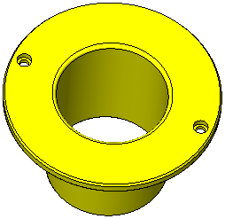
This function creates a new, hidden solid inside a part, tagged as a cutting object and based on the part shape. Small part features such as holes and rounds are eliminated from the cutting object, and offsets can be applied to allow clearance in the pocket where needed.
See the Cutting Object Notes that refer to a cutting object after it is created.
Required Step 1 
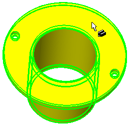
Pick the object for which a cutting object is to be created. Only a closed solid object can be selected.
The system automatically switches to the next required step.
Notes:
-
If the selected object is not closed, a message is displayed informing you that the operation can only be performed on a closed solid object.
-
If the selected object already has a cutting object attribute attached to it, an appropriate message is displayed and you are prompted to either exit the function or to continue.
-
If the selected object contains threads, a message is displayed informing you that the cutting object will be created without the threads.
Required Step 2 
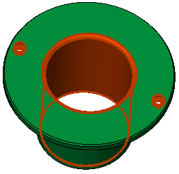
Pick the faces (pockets, holes, rounds) to be removed (on the cutting object) and <exit><exit>.
When switching from required step 1 to step 2, all holes and cylindrical faces are automatically selected. In step 2 you can pick or unpick any face from the selected object.
Required Step 3 
Set the global and local offset values. The following parameters are displayed:
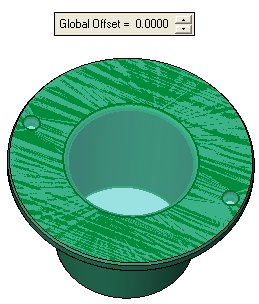
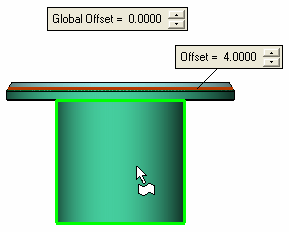
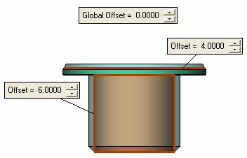
Both, global and local offsets can be defined.
|
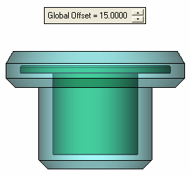
Global Offset only defined. |
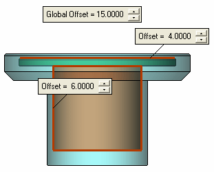
Global and Local Offsets defined. In this case, the local offset defines the offset amount for the selected faces (in other words, the global offset occurs only on faces where a local offset has not been defined). |
|
|
|
To set local offset values for faces, pick multiple faces and define specific offset values for each face.
Examples:
|
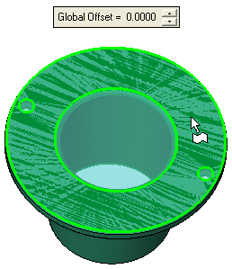
Pick a face where a local offset is to be defined: |
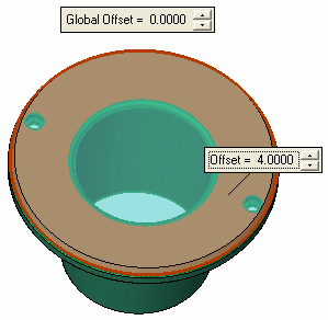
Set the local offset value is the displayed label. The offset amount is immediately previewed. |
|
|
|
|
Pick additional faces as required: |
Set the local offset value. |
|
|
|
In this example the Global Offset = 0.
Optional Step 1 
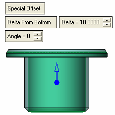
Define the split plane, top and bottom offset and the angle between the offsets. This stage includes the splitting of the selected face, offsetting the faces (with different values for each face) and setting an angle value between the split faces, as shown below for example.
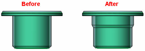
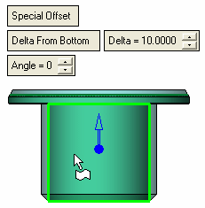
The following parameters are displayed together with a direction arrow:
|
Pick the face to be split and offset: |
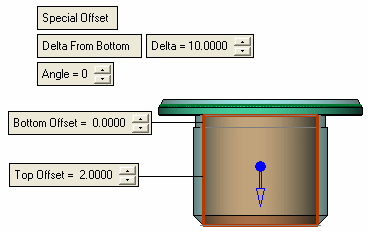
The face is split into Top and Bottom and the following labels are displayed: |
|
|
|
Parameters:
|
Special Offset |
This is a toggle option Special Offset / None that enables you to either display the special offset parameters or to hide them. |
||||
|
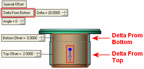
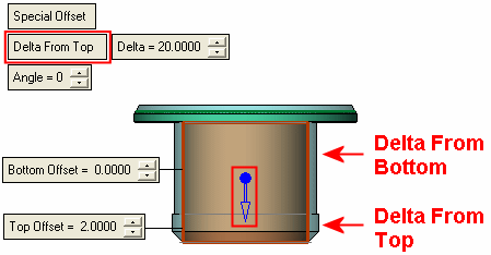
Delta From Bottom |
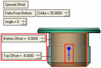
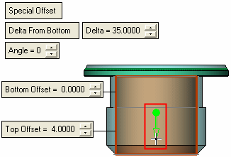
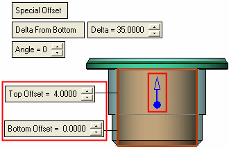
This is a toggle option Delta From Bottom / Delta From Top that defines whether the Delta value is from the top or bottom of the selected face. The top and bottom faces are labelled; the top face is defined as the side in the direction of the arrowhead, see below.
|
||||
|
Delta |
The delta distance of the split from the top or bottom of the selected face. |
||||
|
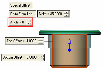
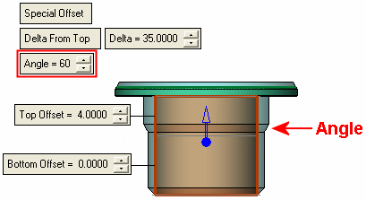
Angle |
The angle at the split of the selected face.
|
||||
|
Top Offset |
The offset of the top face(s) after the split. The top side is defined as the side in the direction of the arrowhead. The top offset must be larger than the bottom offset. |
||||
|
Bottom Offset |
The offset of the bottom face(s) after the split. The bottom side is defined as the side opposite to the arrowhead direction. |
Click the a direction arrow to swap the top and bottom sides of the selected face. The Top and Bottom Offset labels are swapped accordingly.
|
|
|
|
When you have completed the steps, click OK ![]() or Apply
or Apply ![]() in the Feature Guide to complete the function. The cutting object is created.
in the Feature Guide to complete the function. The cutting object is created.
-
The cutting object is hidden by default; press the Hide/Show buttons to hide the part and show the cutting object part.
-
The cutting object attributes are automatically attached to the part.
-
Any cutting object that is created by this function will get the number 1.
When completed, the Cutting Object feature will appear in the Feature Tree as follows:

|


