|
|
Replace Faces  : Options and Results
Access: Open this function from one of the following locations:
-
Select Tools > ECO Tools > Replace Faces from the menu bar.
-
Right-click the All ECO root folder in the ECO Tree and select Replace Faces.
-
Right-click the relevant ECO# folder in the ECO Tree and select Replace Faces.
-
Right-click the relevant comparison folder (in the ECO# folder) in the ECO Tree and select Replace Faces.
-
Right-click the relevant part in the comparison folder in the ECO Tree and select Replace Faces.
Replace faces in the work part with faces of an ECO part to apply an ECO change.
This function replaces faces in one part of the assembly with other part faces (deleting faces from the first part and "importing" faces from the second part).
In a typical system development cycle, the specification or the implementation is likely to change during engineering development or during integration of the system elements. These last-minute design changes are commonly referred to as Engineering Change Orders (ECOs) and affect the functionality of a design after it has been wholly or partially completed.
In general, it is recommended to use the Replace Master Part function at the beginning of the project and the Replace Faces function (which is at the end of the history) at a very advanced project, where the original connection to the master is not so relevant.
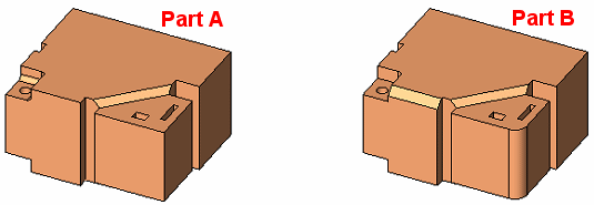
For this example, the following assembly parts are used. These parts would be an original part (A) and an ECO part (B) positioned in the same place (for clarity they are displayed separately below). In step 1, faces are selected to be removed from part A, and in step 2, faces are selected to be added (to part A) from part B.
Notes:
-
If the Replace Faces function is invokedinvoked from a comparison folder in the ECO Tree, the system automatically selects the faces to be removed and the faces to be added.
-
Default ECO comparison colors are defined in the Preferences. The colors set in the Preferences are given to any new comparison. Changes in the ECO dialog do not affect the Preferences.
Required Step 1 
Pick the faces to be removed. Multiple faces can be selected from a single part. See the note above regarding automatic selection of faces to be removed and added.
When no faces are selected, you can pick a face from any part in the assembly. After the first face is picked:
-
The selection of faces from other parts is not possible.
-
All parts (except for the part containing the selected face(s)) become temporarily wireframe.
|
The following parameter is displayed: |
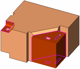
After each selection of a face(s), the outer/inner ("free edges") boundaries/edges (with respect to the Max. Gap value) are displayed in purple. |
|
|
|
|
Max. Gap |
Enter the Max. Gap tolerance to join the objects. This parameter controls the stitch tolerance when healing multiple objects with gaps. The initial default tolerance value is as defined in the Preferences. See the same Preference also for the tolerance range. |
When at least one face is selected, press <exit><exit> to jump to the required step 2.
Required Step 2 
Pick the faces to be added to the part selected in step 1. See the note above regarding automatic selection of faces to be removed and added.
When switching to this step, the part from which the faces were selected in step 1 are displayed in wireframe and all other parts in the assembly are shaded. The "free edges" from step 1 are displayed in purple. This is shown in the example below.
The following parameters are displayed:
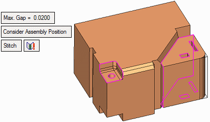
In this stage, you may pick a face(s) from a different part in the assembly, and after selection of the first face:
-
The selection of faces from other parts is not be possible.
-
All other parts in the assembly are temporarily hidden; the part with the 2nd stage selection (part B) is shaded, and the part with the 1st stage selection (part A) remains in wireframe.
|
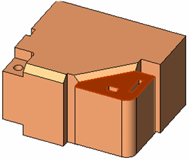
A face is selected from part B: |
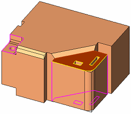
At this point, an analysis is run on all faces from part A and B, and the "free edges" of each part are highlighted. The free edges of part A remain in purple, while the free edges of part B are displayed in yellow. |
|
|
|
Parameter descriptions:
|
Max. Gap |
See the description in step 1 above. |
||||
|
Consider Assembly Position |
This is a toggle option Consider Assembly Position / Don't Consider Assembly Position:
|
||||
|
Stitch |
This is a toggle option, Stitch / Don't Stitch.
|
||||
|
|
This icon indicates that the boundaries of the two face groups do not match. |
||||
|
|
This icon indicates that the boundaries of the two face groups do match. |
Optional Step 1 
Multiple core/cavity options. This step includes options that enable you to control multiple core/cavity solutions, such as copying the changes done in the required steps 1 and 2 above to the other side of a multi core/cavity.
The following options are available in this step:

|
Single |
This option performs no operation other than to prompt you to choose another option. This is the default option. |
|
Multi - UCS to UCSs |
Copy the changes (at the origin UCS location) to multiple UCS locations. This option prompts you to pick an origin UCS and multiple destination UCSs. The multiple UCS locations can be on different instances. |
|
Multi - Mirror |
Copy entities by mirroring them about a mirror surface (planar face or datum plane) or line (or two points to create a line). This option prompts you to pick a plane, planar face, line, or points. |
Note: If you select either the UCS or Mirror option without completing the minimum requirements of the optional step (one origin UCS and one destination UCS or selecting a mirror plane), then switch to required step 1 or 2, a message is displayed informing you that the selected option was not completely defined, prompting you to confirm leaving the step.
Press OK ![]() or Apply
or Apply ![]() in the Feature Guide to complete the function.
in the Feature Guide to complete the function.
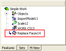
When completed, the Replace Faces feature will appear in the Feature Tree. This feature is created in the part belonging to the faces that were selected in the required step 1 (in this example, this is part A).
|


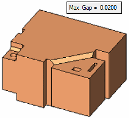
 - Indicates that the stitch operation can be completed.
 - Indicates that the selected faces are not sufficient to create a stitched solid object. See the icon descriptions below.