|
|
Extract Electrode : Options and Results


Access: Open this function from one of the following locations:
-
Select Electrode > Add Electrode > Extract Electrode from the menu bar.
-
Select Extract Electrode from the Electrode Guide.
Extract (create) a new electrode. This involves defining an electrode area which will be the basis for the blank.
This function, together with the Mark Extracted Faces Electrode Preference option, enables you to mark the extracted faces on the insert or plate the electrodes are extracted from, so that you know where electrodes were already created and also to enable you to hide those faces in order to create capping faces over them.
Required Step 1 
Select a reference UCS.
This UCS is very important as it is the reference point on the component for the dimensions, locations and reports for all the electrodes. It is also used to set the component orientation for the EDM process. The Z direction of the reference UCS sets the plane that will be used for the electrode area.
The reference UCS is automatically picked by the system; see the notes below. To change the UCS, return to this stage and pick a different UCS.
Notes:
-
If the selected UCS is not in the main assembly, and is at the same location and orientation as a UCS already used as a reference UCS on the Electrode Tree, then the system will use the UCS already on the tree.
-
If the Extract Electrode function is invoked by right-clicking on a UCS on the Electrode Tree (and selecting the function from the displayed popup menu), then that UCS is used as the reference UCS.
Required Step 2 
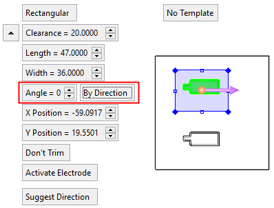
Pick a point to preliminary position the electrode. The following parameters are displayed:
Toggle the parameters expand/collapse button  / / to display sizing and positioning parameters relevant to the shape of the electrode. to display sizing and positioning parameters relevant to the shape of the electrode. |
|||
|
|
|
|
|
Pick a place where you wish to create the electrode and define the parameters.
|
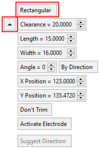
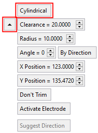
Rectangular |
This is a toggle option that enables you to define the shape of the blank; Rectangular / Cylindrical.
|
||||
|
Clearance |
Define the Clearance height. The clearance is the distance between the highest point under the blank and the bottom plane of the Base. The default of the clearance is set in the Electrode Preferences. |
||||
|
Radius |
Toggle the parameters expand/collapse button The size and position of the blank can be set either dynamically, by entering numeric values (see below) or by setting a direction using the direction arrow. The X Position and Y Position parameters are displayed once an electrode positioning point has been selected. Numeric values examples:Numeric values examples:
Adjust the parameter values as required. The default sizes of the blanks are set in the Electrode Preferences. To define the rotation angle of a cylindrical or rectangular blank, either set the Angle value (entering numeric values manually) or by selecting a Direction (using the direction arrow) to define any direction as the +X direction of the blank. See the example. |
||||
|
Length |
|||||
|
Width |
|||||
|
Angle |
|||||
|
By Direction |
|||||
|
X Position |
|||||
|
Y Position |
|||||
|
Trim |
This is a toggle option that enables you to specify which faces are to be attached to the extracted electrode; Trim / Don't Trim. When the Trim option is selected, the Blank Offset option is also displayed. See the examples below for using Trim and Blank Offset, when Blank Offset = 0 and when Blank Offset > 0. |
||||
|
Activate Electrode |
This is a toggle option Activate Electrode / Don't Activate Electrode, that enables you to control whether or not to activate the electrode after it is extracted. The default setting for this parameter is set in the Electrode Preferences. |
||||
|
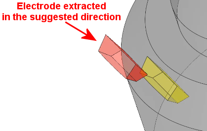
Suggest Direction |
Let the system find the optimum orientation direction.
When this option is selected, the system finds the optimum electrode extraction direction. The result may change the direction arrow indicating the new system-suggested extraction direction. In addition, the By Angle direction function is displayed, enabling the direction angle to be fine tuned.
This option is available if faces are attached to the electrode (these faces are colored green). Note: It is recommended to use stitched faces for direction suggestion. |
||||
|
Apply Template |
This is a toggle option Apply Template / No Template that enables you apply a predefined electrode template to the electrode while it is being created. |
Define an electrode area
-
Create either a rectangular or cylindrical electrode area.
-
Edit the electrode area (either dynamically, by entering numeric values or by using a reference line) to position it approximately where you wish to create the electrode. Any face that is completely included within the electrode, will be colored red. Such a face is considered a candidate for attachment to the electrode.
-
If required, attach the faces to the electrode area. The attached face is displayed in green.
-
If faces are not attached they may be attached later, when editing the extract feature. In this case, when editing an electrode that has no faces attached to it, all non-electrode parts are displayed to show faces that may be candidates for attachment (to the electrode).
If faces are not attached, solid electrodes can be created (by creating the appropriate solid geometry).
Notes:
-
Flipping or changing the electrode direction does not effect the orientation of the mold component.
-
If red faces are displayed but no green (attached) faces, and you click OK
 in the Feature Guide, a message informs you that no faces were attached to the electrode (it will be created empty) and prompts you to attach faces.
Using Trim and Blank Offset = 0 when creating the electrode areaUsing Trim and Blank Offset = 0 when creating the electrode area
Use Trim when creating the electrode area to specify which faces are to be attached to the extracted electrode. When Trim is selected, an additional option Blank Offset is displayed (with a default value of 0).
For example:
-
-
Pick the three faces (see below) you wish to be part of the electrode and attach them.
-
-
-
Those parts of the faces which intersect the blank preview are then trimmed and attached to the extracted electrode.
-
|
|
|
|
The finished electrode will look like this: |
|
|
|
|


Using Trim and Blank Offset > 0 when creating the electrode areaUsing Trim and Blank Offset > 0 when creating the electrode area
Use Trim with a defined Blank Offset when creating the electrode area to create a blank with a slight offset from the original definition of the Burning Area. This allows you to define the Burning Area according to the trim size, without a direct impact on the size of the blank. It also creates a blank which is bigger in all directions in the offset value.
|
Blank Offset defined as 0: |
Result: |
|
|
|
|
Blank Offset defined as > 0: |
Result: |
|
|
|
Editing the Electrode Area DynamicallyEditing the Electrode Area Dynamically
To dynamically edit the electrode area, pick one of the locations listed below and start dragging immediately.
|
Move
|
|
|
Re-Size
|
|
|
|
|
Rotate
|
|


Editing the Rotation Angle by setting a direction using the direction arrowEditing the Rotation Angle by setting a direction using the direction arrow
To define the rotation angle of the blank, either set the Angle value (entering numeric values manually) or by selecting a Direction (using the direction arrow) to define any direction as the +X direction of the blank.
In the examples below, the Angle value is initially 0.
-
-
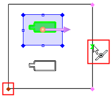
Press the By Direction button; the direction arrow is displayed.
-
-
-
Set the direction using one of the Direction Arrow options; in the example below, the option By 2 Points from the direction arrow toolbar.
-
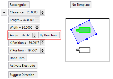
The electrode area is rotated to the defined angle and the Angle parameter is automatically filled with the new angle value.
Attaching FacesAttaching Faces
Any face that is completely included within the electrode, will be colored red. Such a face is considered a candidate for attachment to the electrode. Attached faces are displayed in green.
To attach a red face to the electrode area, press the middle mouse button.
|
|
|
The attached face is displayed in green.
|
|
|
To unselect a red face, use standard Cimatron tools (Pick, Unselect All and Unselect by Box).
To detach green faces, pick the face (you can also use Pick by Box).
The electrode direction represents the motion direction of the electrode. This direction is used as the default direction for all extensions. By default, the direction is set to the + Z direction of the reference UCS. This is represented by an arrow next to the reference UCS and may be edited to suit the motion direction of the electrode.
Notes:
-
Flipping or changing the electrode direction does not effect the orientation of the mold component.
-
If red faces are displayed but no green (attached) faces, and you press OK
in the Feature Guide, a message informs you that no faces were attached to the electrode (it will be created empty) and prompts you to attach faces.
Optional Step 1 
Center the electrode area over the attached face. The size of the electrode area remains the same.
|
Before:
|
After:
|


Optional Step 2 
Fit the electrode area to the attached face with a predefined offset. The size of the offset around the attached face is defined in the Electrode Preferences.
|
Before:
|
After:
|


Click OKOK![]() or ApplyApply
or ApplyApply![]() in the Feature Guide to complete the function.
in the Feature Guide to complete the function.
Note: If you click OK when there are red faces selected and no green faces, no faces were attached to the electrode and an empty electrode is about to be created. In this case, a warning message is displayed.
-
Click YES to create the empty electrode.
-
Click NO to reactivate the function.
Use the middle mouse button to attach the faces then click OK
again.
A UCS is created in the middle of the burn faces.
When completed, the Electrode feature will appear in the Assembly Tree, Electrode Tree and the Feature Tree.
Assembly Tree |
|
|
By default, when the electrode is created, it is Fixed |
To move the electrode you need to Float |
|
|
|
Electrode Tree |
Feature Tree |
|
|
|
 onto the defined location and cannot be moved. This is shown in the Assembly Tree.
 it first. (The fix/float status cannot be changed if the electrode is active).

|