|
|
M-Views - Creating: Options and Results

Access: To create a new M-View, click the M-View tab in the Tree Pane, right-click and select New M-View.
Creating M-Views allows you to easily group together display parameters or sets.
Required Step 1 
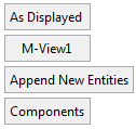
Set the projection of the M-View, zoom, pan and rotate (ZPR), and parts filter. Set the parameters. The following parameters are displayed:
|
|
|
|
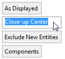
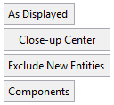
As Displayed |
This is a toggle option As Displayed / By Sets:
|
||||
|
<M-View Name> |
The name of the M-View. Click this button to enter a new name. |
||||
|
Append New Entities |
This is a toggle option Append New Entities / Exclude New Entities:
|
||||
|
Components |
This is a toggle option Components / Entities that enables you to control the visibility of entities or components in an assembly M-View. This option is displayed in the Assembly environment and affects the Drafting (when M-Views are used).
A Preference option defines the default for this parameter. |
In the examples below, M-Views are to be created for the following:
As Displayed
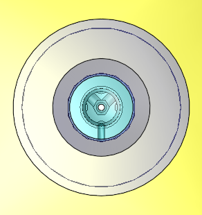
Create a view by defining zoom, pan and rotate of the part or assembly. The Hide/Show status of all objects and components is kept as it was when the M-View was created.
|
Demo: Press the button below to view a short movie demonstrating the function: |
|
|

-
Toggle the By Sets/As Displayed button to As Displayed.
-
Assign the name Close-up Center to the M-View:
-
Zoom, Pan and Rotate the part accordingly. In this example, a close-up view of the center is created:
|
|
|
-
Press OK
 to complete the action. (The orientation of the geometry is set when the OK button is clicked).
The newly-created M-View is listed in the M-View Tab.
By Sets
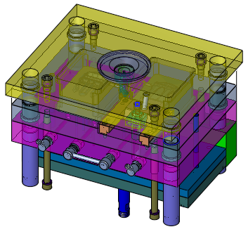
The Hide/Show status of objects and components is determined by selecting which sets are ON and which are OFF.
|
Demo: Press the button below to view a short movie demonstrating the function: |
|
|
-
Toggle the By Sets/As Displayed button to By Sets. The Set Filter dialog is displayed:
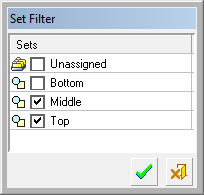
-
Select the sets which will comprise the M-View. In this example, the upper middle and top layer are selected. Press OK
in the Set Filter to apply the selected sets.
|
|
|
-
Assign the name Middle & Top to the M-View:
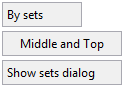
To re-open the Part Filter to mark additional sets, click the Show sets dialog button.
-
Press OK
to complete the action.
The newly-created M-View is listed in the M-View Tab.
Optional Step 1 
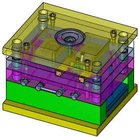
This option lets you pick a sketched line which becomes a section line that automatically sections the part or assembly.
|
In this example, the assembly has been sectioned by a jagged line. |
You can also flip the sectioned side by clicking the section line arrows: |
|
|
|
In addition, when working with a broken section line, the bold portion determines the projection side of the part when viewed in Drafting as a D-View. (It has no significance in the Part environment). It can be flipped by clicking on the bold line:
|
|
|

The newly-created M-View is listed in the M-View Tab.
Note that the M-View's icon ![]() in the M-View Tab indicates that the view contains a section. Toggling the Section Line button
in the M-View Tab indicates that the view contains a section. Toggling the Section Line button ![]() in the M-View Tab changes the M-View to section mode.
in the M-View Tab changes the M-View to section mode.
You can define three different shade modes for the sectioned face, defined in the General Preferences M-View Section dialog as follows:
Notes:
-
You must ensure the Global Mixed Render Mode
 button is selected to view the different shade mode options.
 -
You can view the shade mode by toggling the Section Line button
 in the M-View.
 -
While creating a section M-View, each part is displayed with a different hatch (spacing and/or angle). These hatches are used to distinguish between the different parts in the assembly (neighboring components have different hatches).
|
Opaque: This option defines the sectioned faces with 0% transparency as shown below: |
Semi Transparent: This option defines the sectioned faces with 50% transparency as shown below: |
|
|
|
|
Transparent: This option defines the sectioned faces as 100% transparent (in this case the hatches are not displayed) as shown below: |
|
|
|
Optional Step 2 
This Section Off List step allows you to pick which components will be excluded from the section.
|
Demo: Press the button below to view a short movie demonstrating the function: |
|
|
|
In this example, one of the Raisers is picked for exclusion: |
The component is highlighted for exclusion. Additional components can be picked: |
|
|
|
|
The components are highlighted for exclusion: |
Upon returning to the Optional Step 1, the selected components are not sectioned: |
|
|
|
Components can also be removed from the Section Off List:
|
Pick the components to be removed from the Section Off List: |
|
|
|
|
|
The component is not highlighted for exclusion. Additional components can be picked: |
There are no components in the Section Off List (all components are sectioned): |
|
|
|
|