|
|
Modify By Sketcher 
Access: Open this function from one of the following locations:
-
Click the
 button in the toolbar.
 -
Select Faces > Main Tools > Modify By Sketcher from the menu bar.
-
Select Parting Surfaces > Modify By Sketcher from the Mold Design Guide Toolbar or Parting Guide Toolbar.
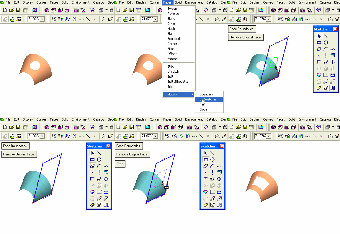
Modify the boundaries of a face by projecting them onto a plane and manipulating them with the Sketcher tools.
The picked face and its boundaries are presented as a sketch with the origin of the UCS positioned at the corner U=0, V=0 or the closest corner to it (from which the X and Y directions are taken).
Splines are treated as "Control Points" splines for improved editing capability.
|
Demo: Press the button below to view
a short movie demonstrating the function:
|
Practice: Press the button below to open Cimatron with a practice ELT file similar to that used to create the movie (if the relevant feature already exists in the ELT file, you can either edit it or delete it and create a new feature). |
|
|
|
General Interaction
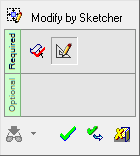
The following is the Feature Guide for Modify by Sketcher.
|
|
|
Required Step 1
![]() : Pick the face to be modified.
: Pick the face to be modified.
Required Step 2
![]() : Set the modification parameters and modify the sketch as required.
: Set the modification parameters and modify the sketch as required.
Required Step 1 
Pick the face to be modified.
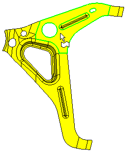
Once a face is selected, the next step in the Feature Guide is invoked.
Required Step 2 
Set the modification parameters and modify the sketch as required. A sketch of the face is displayed together with the function parameters, the Sketcher functions and the Sketcher Tools toolbar, as follows:
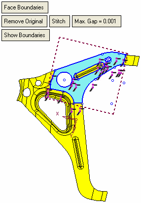
Note: The boundaries are automatically displayed by default, these boundaries can be removed, as described in the next step.
Modify the sketch as required. Set the parameters as required:
|
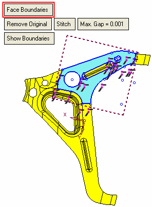
Face Boundaries |
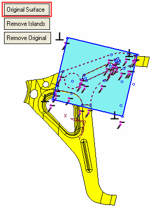
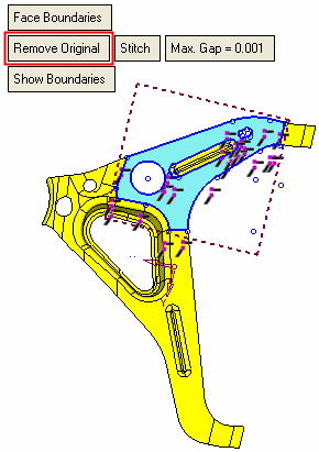
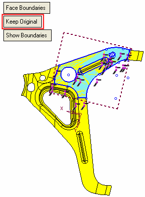
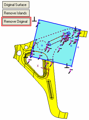
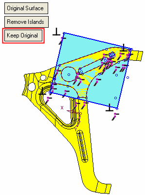
This is a toggle option Face Boundaries / Original Surface that enables you to perform operations either on the face boundaries or on the original surface. Face Boundaries is the default option. The original surface is calculated in the minimum parametric box as + 5% of the face. The limits of the original face can be modified by manipulating the box. If modified contours intersect the boundaries of the original surface, it is enlarged accordingly. Each of these options displays different parameters, as shown in the examples below.
|
||||||||||||||||
|
Remove Original |
This is a toggle option Remove Original / Keep Original that enables you to either remove the original face (leaving only the modified face) or to keep both the original and modified faces. Remove Original is the default option.
If the Face Boundaries and Remove Original options are selected, additional parameters are displayed:
Note: If the face being modified is the only face in the body (a body which has a single face), the Stitch / Do Not Stitch toggle option is grayed out with the Do Not Stitch option displayed. |
||||||||||||||||
|
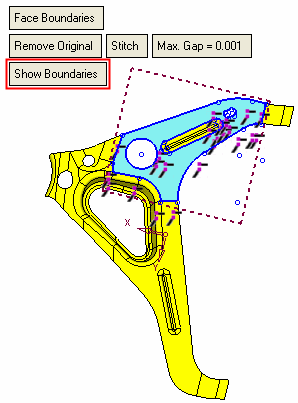
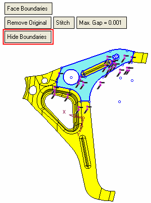
Show Boundaries |
This is a toggle option Show Boundaries / Hide Boundaries that enables you to show or hide all boundaries. This option appears if the Face Boundaries option is selected, above. Show Boundaries is the default option.
|
||||||||||||||||
|
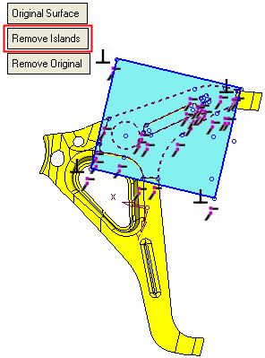
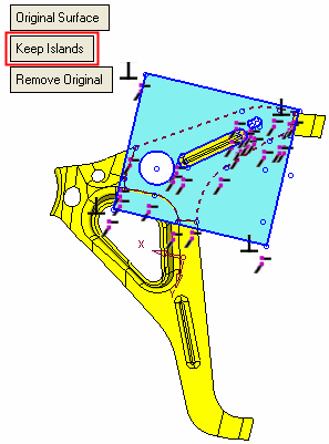
Remove Islands |
This is a toggle option Remove Islands / Keep Islands that enables you to remove or keep any islands that exist in the original surface. This option appears if the Original Surface option is selected, above. Remove Islands is the default option.
|
||||||||||||||||
Notes:
-
The Preview in the Feature Guide is set to Automatic Preview, and grayed out (unavailable).
-
If you go back to the first stage and select a different face, you lose all changes. However, the parameters in the second stage remain as they were defined.
-
if you go back to the first stage while in edit mode, you may only select faces from the same part.
Click OKOK or ApplyApply in the Feature Guide to complete the function. The Boundary-Sketch feature will appear in the Feature Tree as follows:

For more, see Editing a Sketch.
|


