|
|
New Direction: Solid-Based Analysis

Access: Open this function from the following location:
-
Invoke the New Direction function and, from the displayed screen parameters, select the toggle option Analyze By Solid & PS Part.
Invoke the QuickSplit function and create a new opening direction.
Perform the split direction analysis using solid-based (topology) analysis to assign QuickSplit directions. This topology analysis is performed on solid and parting surface parts and is based on solid data from both closed and open solids. See the Solid-Based Analysis parameters below.
Cimatron’s solid-based parting (for both closed and open solids) includes QuickSplit modes offering the following advantages:
-
Faster, more effective preliminary split.
-
Analysis tools to speed up mold tool design (by evaluating parting surfaces).
The solid-based (topology) analysis tools in the parting environment can help you to dramatically shorten the mold tool design process (in the assembly environment), allowing you to handle more complex jobs effectively, and to shorten the overall delivery times of projects. These tools help you to increase the quality of active parts by identifying and helping to repair faults (gaps and mismatches) in solid objects. Active parts that have fewer faults result in:
-
Faster, easier modeling and tool design.
-
Avoiding mistakes.
-
Successful regeneration.
-
Earlier start for manufacturing of the mold (NC programming, Milling, Wire EDM) because pockets for inserts or lifters can be added to the core and cavity even before exporting parting surfaces. Electrode design can also start earlier.
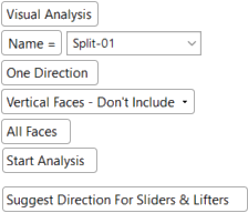
The parameters that are displayed and the type of analysis performed, depend on the toggle option selected Visual Analysis / Analyze By Solid & PS Part. The following parameters are displayed (see the note below regarding the availability of these parameters):
|
For solid-based (topology) analysis, the parameters below are displayed (see the note below). Toggle the parameter Analyze By Solid & PS Part to display . . . |
. . . the Visual Analysis parameters. |
|
|
Note: If you have a MoldDesign license, the default parameters are as displayed above. |
|
|
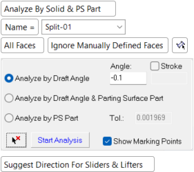

Solid-Based Analysis parameters
|
Name |
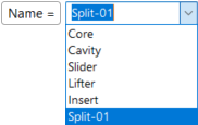
When creating or editing a split direction, you can either type in a name for the direction or select a name from a predefined list.
The predefined list of split direction names is defined in Preferences. The default name that appears in the parameter field is that created currently by the name generator (according to the parameters set in Preferences). When selecting a name from the list, it is displayed in the parameter field with an index number. The number of digits in this index number is defined in Preferences by the parameter, Number of Index Digits. Click the parameter list field to edit the currently displayed name. |
|||||||||||||||||
|
All Faces |
Toggle option to determine which of the relevant faces are to be included in the split direction set, including all faces in the analysis or ignoring previously assigned faces.
|
|||||||||||||||||
|
Analyze by Draft Angle |
This is an analysis option. This analysis option is a preliminary split that uses topology (solid data from both closed and open solids) to assign QuickSplit directions. Any unassigned surfaces are real undercut surfaces that require mending or lifters/sliders/etc. This option assigns all faces based on draft angles, except where there are undercuts and a lifter is necessary.
The Angle parameter can be set if this option is selected (see below). |
|||||||||||||||||
|
Analyze by Draft Angle & Parting Surface Part |
This is an analysis option. This analysis option enables you to evaluate the integrity of the parting surfaces in terms of how well they are aligned with the parting line. This mode checks that parting faces match their corresponding QuickSplit directions and identifies places where the parting surfaces are incomplete, making it easier for you to address any issues. Here the Analyze By Draft Angle & Parting Surface Part mode has found an area where internal parting surfaces are missing.
The Angle and Tol. parameters can be set if this option is selected (see below). |
|||||||||||||||||
|
Analyze by Parting Surface Part |
This is an analysis option. This analysis option enables you to evaluate the integrity of the parting surfaces in terms of how well they are aligned with the parting line. This mode is the final check of parting surface integrity. If the check is successful, then the active skin (smoothly joined QuickSplit Faces and Parting Surfaces) is watertight and can be used to create solid active parts, saving a considerable amount of time in the assembly environment. Here the Analyze By Parting Surface Part mode shows that the surfaces below the parting line remain green, while surfaces above the parting line have been selected. This means the user is working with a watertight active skin that can be used to create solid active parts:
The Tol. parameter can be set if this option is selected; see below. |
|||||||||||||||||
|
Angle |
The Angle parameter enables you to control the draft angle on which the analysis is based. This determines whether or not a face is selected for inclusion in the split direction set. For each face, if the Normal direction of the face with respect to the split direction vector, is less than or equal to 90 degrees minus the Angle parameter value (Normal to split direction ≤ (90 - Angle)), then the face is selected for inclusion in the split direction set. If it is greater, then the face is not selected. This can be seen in the examples below using the following part:
In the examples below, the Angle parameter is used to determine whether or not a face is selected for inclusion in the split direction set:
This parameter is grayed out (not available) if the option Analyze by Parting Surface is selected. |
|||||||||||||||||
|
Stroke |
The Stroke option enables you to limit the examined area for partial undercuts. It is used for analyzing faces that belong to lifters by defining the stroke (the motion distance of the lifter), where an unlimited distance would result in a collision. For example, in the image below, the blue face is defined as having an undercut, because, when looking at its opening, we can see that it cannot be fully extracted as there is a face blocking it. In this case, by limiting the motion distance of the lifter, a collision can be avoided.
When the Stroke checkbox is selected, a value field becomes available. The default value is 50mm or 2inch, for mm or inch parts respectively. By default, the checkbox is unselected. This parameter is available if the Analyze by Draft Angle option is selected. |
|||||||||||||||||
|
Tol. |
The Tol. parameter enables you to control the tolerance on which the analysis is based. This determines whether or not a face is selected for inclusion in the split direction set. If a face (being checked for inclusion in the split direction set) has a common edge with a parting surface, and the distance of the common edge from the checked face is less than the defined tolerance value, the face selection stops at the common edge. This parameter is grayed out (not available) if the option Analyze by Draft Angle is selected. |
|||||||||||||||||
|
|
Use the Clear Selection button to clear (unselect) all selected faces. |
|||||||||||||||||
|
Start Analysis |
Start the solid-based (topology) split direction analysis to assign QuickSplit directions. |
|||||||||||||||||
|
Show Marking Points |
This checkbox option enables you to Show/Hide marking points.
The default color of marking points is purple. However, marking points that mark the purple edges of yellow faces (undercut edges), are displayed in cyan, as shown in the example above. |
|||||||||||||||||
|
Suggest Direction for Sliders & Lifters |
Let the system find the optimum orientation direction. This finds the best opening direction of selected Slider and Lifter faces. This takes into account all selected faces and finds the direction with the least amount of undercuts. This is especially useful when all the faces of a slider or lifter have draft angles and the opening direction is very hard to define for them. When finding the optimal direction for the selected faces for the Sliders and Lifters, the result may change the direction arrow indicating the new system-suggested direction. In addition, the By Angle direction function is displayed, enabling the direction angle to be fine tuned. Notes:
|
 /
/  ) enables you to highlight these faces for better visualization.
Operations
Set the parameters.
Define the split direction(s) using the directional arrow.
Notes:
Pick a face in the relevant direction.
Start the analysis.
Optionally, perform a Direction Analysis and/or manually define faces to always be included in the parting direction.
See also:
New Direction: Surface-Based Analysis
New Direction
New Direction: Option and Results
|