|
|
Surface Roughness PMI 

Access: Open this function from one of the following locations:
-
Click the
button
in the toolbar. -
Select Tools > PMI > Surface Roughness from the menu bar.
Create PMI Surface Roughness symbols and assign them to appropriate entities.
Creating the PMI Surface Roughness symbols in the Modeling environment is very similar to creating the Surface Roughness symbols in the Drafting environment. The main differences are as detailed in PMI & Drafting.
|
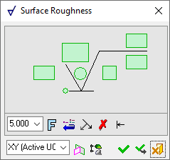
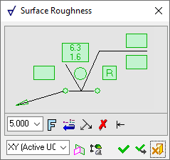
The dialog for the symbol is displayed.
The symbol dialog is initially displayed grayed out until the symbol is positioned in the graphics window.
|
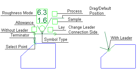
The image below shows an example of the symbol with each element labeled.
|
|
|
|
The procedure below describes how to create this symbol in Cimatron.
Annotate the symbol either in the dialog or in the graphics window (once the symbol has been positioned).
For a description of the symbol elements in this dialog, see the Dialog Structure.
Leader/Symbol Creation Order:Leader/Symbol Creation Order:
When adding a symbol, the creation order of the symbol location and leader are defined as follows:
Adding a free symbol: When adding a symbol (without first selecting an entity), the first click defines the symbol location and the second click creates the leader.
Adding a symbol to a selected entity: When adding a symbol to a selected entity, the first click creates the leader and the second click defines the symbol location.
Working with PMI Surface Roughness
Surface Roughness symbols that can be created in the Drafting environment can also be created using the PMI Surface Roughness function.
Add a PMI Surface Roughness symbol
-
InvokeInvoke the PMI Surface Roughness tool. A default, grayed-out PMI Surface Roughness dialog is initially displayed.
-
Pick the entity to be annotated.
|
The part before an entity is picked. |
The part after an entity is picked. |
|
|
|
After you pick the entity, a transparent plane is displayed and the PMI symbol is displayed on the plane (initially at the picked point). The plane (that the PMI symbol and annotation will be created on) is parallel to the XY plane of the active UCS and its Z coordinate traverses the picked point or the start point of the picked edge.
-
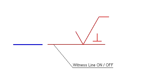
Position the Surface Roughness symbol by picking a location on the screen.
|
The Surface Roughness symbol is displayed on the plane. |
After positioning the symbol, the default dialog that was initially displayed when you invoked the tool now shows the relevant information. |
|
|
|
Note: The Surface Roughness symbol is created in the plane indicated in the bottom-left corner of the PMI Surface Roughness dialog and is associated with the picked entity. See PMI Associativity below.
-
Edit the Surface Roughness parameters, if required, as explained in Surface Roughness in the Drafting environment.
-
Re-position the symbol/annotation, if required, either by picking another location or by dragging it to the new location.
-
Close the PMI Surface Roughness dialog by clicking the appropriate approval option (or by clicking the MMBMMB anywhere outside of the dialog).
|
|
OK: Accept the changes, perform the operation, and close the current dialog/task. |
|
|
Apply: Accept the changes, perform the operation, and keep the current dialog/task open. |
|
|
Cancel: Cancel all changes and close the dialog/task without saving the settings. |
To edit (or to re-position) a symbol after it has been created:
Double-click the appropriate symbol. The relevant dialog associated with the symbol is displayed. This means that you are now in edit mode.
Edit the symbol elements and/or re-position the symbol as required.
PMI Associativity
A PMI is fully associated with the model - changing the model shape is reflected automatically in the PMI. A PMI that loses associativity remains in its last position and changes color.
|