|
|
Activate PMI M-View 

Access: Open this function from the following location:
-
Select Tools > PMI > Activate PMI M-View from the menu bar.
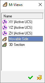
Activate a previously created M-View to re-orientate the display to the plane of the selected M-View. All new PMI is now created in this plane.
The M-Views dialog is displayed showing the list of M-Views currently available in this file:
|
|
Select the required M-View and press OK. |
Working with M-Views
The following example shows how to use M-Views when creating PMI.
-
Pick an appropriate face.
-
Click the Rotate to Plane icon from the toolbar. The picked planar face is displayed parallel to the display plane (screen).
-
Click the M-View tab in the Tree pane and create a new M-View.
-
InvokeInvoke the Activate PMI M-View tool. The M-Views dialog is displayed:
-
Select the new M-View you just created and click OK.
From this point onwards, the projection of this M-View is the default projection for all new entities, for example:
|
The transparent plane, which appears when creating a PMI dimension, is on the same plane as the picked face . . . |
which means that dimensions are created in the plane of the face. |
|
|
|
Dimensions cannot be created for entities that are not on the same plane as the active M-View. For example, if you pick the circle indicated below, you cannot created the dimension as the transparent plane is parallel to the face (with 2 holes) that was used do define the M-View (notice that the active M-View in the PMI Dimension dialog also confirms this).
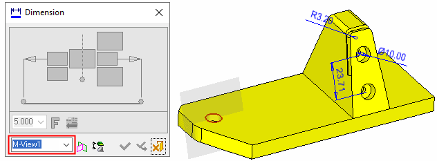
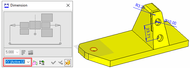
In this case, to create the new dimension, you can either exit the PMI Dimension tool and activate a different PMI M-View from the M-Views dialog, as described above, or change the projected plane from within the PMI Dimension dialog by selecting the appropriate M-View from the dropdown list:
You can now create the dimension:
|
In this case a radial dimension is created: |
Changing the M-View to YZ (Active UCS) creates a different dimension; in this case a linear dimension: |
|
|
|
-
Double-click the M-View in the tree pane. This re-orientates the display to the plane of the M-View and also displays all other entities associated with the M-View:
The following display appears:
|
In this case, the lower dimensions are not in the plane of the red face (or parallel to the face). These lower dimensions can be excluded from the M-View by right-clicking on the M-View in the tree pane and selecting the following option from the popup menu: Exclude Not-Fully Projected PMI from the M-View. |
Approve the change and double-click the M-View again to observe that the lower dimensions are not displayed, as they no longer belong to this M-View. |
|
|
|
|