|
|
NC Setup Report  : Standard - Creating/Customizing NC Reports

Access: Open this function from one of the following locations:
-
Select NC Process > Post & Report > NC Report from the menu bar.
-
Click the NC Report button
in the NC Guide. -
Click the NC Report button
in the Job
Manager. -
Right-click on an item in the Process Manager, or anywhere in the graphics window when no procedure is active, and select NC Guide Commands > NC Report from the popup menu.
The explanation below describes how to create/customize NC Reports. However, a similar procedure is used for other Cimatron reports, such as:
- CMM Report
- Engineering Change Order (ECO) Report
- Electrode Report (from NC)
- Measurement Report
- Tools Report (from NC)
On this page
- General Information
- Creating a Report from Cimatron
- NC Setup Report Template - MHT
- Tools Report Template - MHT
- Reports - PDF
- NC Setup Report Template - Excel
- Change the picture name in an Excel NC Report template
- Change the picture name in an XLSX NC Report template
- Tools Report Template - Excel
- NcReportImage.xml
- General Structure
- Editing the File
- Creating More Reports
- Typical Procedure and Tool Variables
- Additional Variables & Information
- Troubleshooting MHT Format Templates
- Setting an Image in MHT while Editing with Office 2007 or Newer
General Information
An NC documentation mechanism is available which can be freely adapted by the customer. A number of output formats are available and, depending on the chosen file format, the generated report will be opened in the appropriate viewer (see the Standard Report for the list of supported output formats and their relevant viewers). This permits output of different reports to fit the specific requirements of machines and/or customers. The default format is HTML. It is possible to integrate pictures that are provided by the user, and be selected according to the report.
The default viewer for viewing NC Report output files can be defined in the Preferences.
It is possible to also generate a toolpath (TP)-based report, different from the procedure-based report that was available prior to this version. As a result of this, the report templates need to be different. However, the older mechanism and report templates are still supported. In order to differentiate between new and old, the new report templates MUST include the digits "10" as the last 2 digits in the template name. This is the trigger that will let the system know that the new report has to be generated.
The report structure is determined by template files that are placed in the folder:
...\ProgramData\Cimatron\Cimatron\2026.0\Data\NC\Customized Reports
Supplied with the installation of Cimatronare examples of such Templates called "Demo_NCSetup10.mht" and "Demo_Tools10.mht" for the MHT format report, as well as "Demo_NCSetup10.xls" and "Demo_Tools10.xls" for the Excel format. For the PDF format there are no special templates, since for PDF the MHT report is automatically converted once generated.
"Demo_NCSetup10" is the template name for the general report and "Demo_Tools10.<ext>" is the template name for a separate tools report that can be created automatically along with the NC Setup Report in the same output folder.
For example, "Demo_NCSetup10.mht" and "Demo_Tools10.mht" create:
<file name>.<TP name>.Report-Post.Setup.mht
<file name>.<TP name>.Report-Post.Tools.mht
Or if the name is changed in the interaction dialog box:
<input name>.Setup.mht
<input name>.Tools.mht
The various parameters are set in ...\ProgramData\Cimatron\Cimatron\2026.0\Data\NcReportImage.xml
Creating a Report from Cimatron
In the report dialog there is the option to select the appropriate output format. A number of output formats are available and, depending on the chosen file format, the generated report will be opened in the appropriate viewer. See the Standard Report for the list of supported output formats.
|
|
With the NC Setup Report you can integrate the picture that is displayed at the time of the report creation. This picture is captured from the screen when the report is created. A rectangle appears in the Display Area. Use "ZPR", set views or save M-Views to place the geometry so that the desired view will appear in the NC Setup Report. Note that dialog boxes or any other item in the rectangle will be captured.
More pictures can be added, if they are captured in advance. This is done by using the function Capture Report Images which can be found in the NC-Process menu. The Capture Report Images dialog is displayed. In this dialog, the pictures that are available for the given Report are listed in the Picture dropdown list.
These additional pictures must first be defined in the XML file and added to the Template. How to do this will be discussed later.
Using the "By Frame (1:1)" Capture Zone, the rectangle is used to define the captured area. Or the "Entire Window" can be captured and the view is scaled to fit the dimensions. This will reduce image quality and can cause the image to be distorted if the Height/Width ratio defined in the XML file is different than that of the Display Area.
NC Setup Report Template - MHT
The report template is created with Microsoft Word and "Saved as" *.mht file.
The mht file can later be opened with Microsoft Word for further editing. For backward compatibility issues, it is recommended to develop the template using Word 2003.
In case the template is developed with Word 2007 or later, the following has to be done with each save:
-
Click Save As>Other Formats.
-
Set the format as 'Single File Web Page (*.mht, *.mhtml)'.
-
Click Tools>Web Options….
-
In the 'Web Options' dialog switch to the 'Encoding' page and select 'Unicode (UTF-8)'.
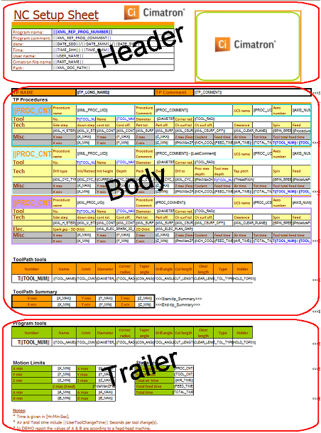
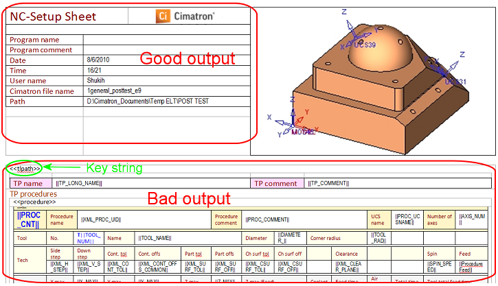
This template is basically divided into three major sections (example NC Setup Report):

Header
This section contains one table and can include strings, variables and pictures. This is a general information area. It is impossible to output TP/Procedure-related information in this area.
Body
This is the section to output TP/Procedure-related information. In order to support a TP oriented output it has a special structure as shown below.
|
<<tlpath>> |
||||||||||||||||||||||||||||||||||||||||||||||
|
||||||||||||||||||||||||||||||||||||||||||||||
|
|
||||||||||||||||||||||||||||||||||||||||||||||
|
|
This section contains some nested tables. Each table has a special key-string in its first (upper left) cell. Note that the key-string can be added to the first cell with any other text or variable. The key-string is not output in any case.
The main table is the TP table, key-string <<tlpath>>. Nested in it there is the procedure table - <<procedure>>, TP tools table - <<tlp_tools>> and TP summary table - <<tlp_summary>>.
Note that the system looks for these special key-strings in order to realize which table to output. Each table is output as a whole, regardless of its content.
With the above structure, for each TP the <<tlpath>> table will be output.
Inside the TP table and repeatedly according to the number of procedures reported, for each procedure the <<procedure>> table will be output. The output for the procedure will include only one of the 3 nested tables, each containing the relevant procedure data:
-
For a general milling procedure, the <<mill>> table is output.
-
For a drilling procedure, the <<drill>> table is output.
-
For a milling procedure where 'Electrode Machining' is checked, the <<electrode>> table is output.
After the last procedure in the TP the system outputs the <<tlp_tools>> table. This table contains a list of all the tools that were in use in the current TP.
The last table to be output is <<tlp_summary>>. It can contain all TP related summary data, such as motion range, time data, etc..
Notes:
-
The last 2 tables are not mandatory.
-
If any titles are needed throughout the body area of the NC-Report, it is recommended to add them in-between the tables, to prevent their unnecessary duplication.
Trailer
General information and tallied results of variables is output in this section. It contains 2 tables. The <<tools>> table contains a list of all the tools in use throughout the whole program. The last table is <<file_summary>>. It can contain file summary data, such as motion range, time data, etc., to summarize the whole report.
Formatting
Text inside and between the sections can be formatted freely. Any attribute (size, color, style, etc.) can be used for the descriptive text or variables globally or individually.
Variables
Variables are differentiated by the "||" mark at the beginning and the end. If a variable contains no value at the time of the creation of the NC Setup Report, nothing is output.
Important - no spaces or other symbols are allowed between the variable name and the "||" mark on both sides!
-
A list of the typical variables can be found in Appendix 1.
-
Defining new variables is described in Appendix 2.
Integrating Pictures
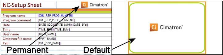
The system recognizes three types of pictures in the NC Setup Report.
-
Permanent – This is any picture that can be inserted in the MHT file in the normal method of the editor. For example this can be the logo of the company that will appear on every report. The name of this picture file is not significant.
-
Default – This is the picture that is captured by the system while generating the NC Setup Report. Its dimensions are set in the XML file. This picture must first be saved with the name "NcReportGeneralImage.jpg" before being inserted into the MHT file. This is automatically done while the report is generated.
-
Pictures from List – These are the pictures saved with the Capture Report Images mechanism according to the names in the "PictureList" branch of the XML file. Similar to the Default, a dummy picture of the right dimensions (the Width and Height in the XML) needs to be created and saved as NcReportGeneralImage@[picturename].jpg (where the [picturename] is the name in the picture list. In case the report is created without having the additional pictures captured, the dummy picture is inserted. So it is recommended that the picture contain meaningful data i.e.: "Capture Stock Image using the 'Capture Report Images' application".
See Appendix 4 - Setting an Image in MHT while Editing with Office 2007 or Newer.
Tools Report Template - MHT
A Tools Report template is basically the same as a NC Setup Report template but it is tool-related rather than procedure-related. Here the information in the Body section is repeated for each tool, rather than for each procedure.
The same three sections (Header, Body and Trailer) exist. The structure of the Body area is slightly different than with the NC Setup Report. The body section contains only one table, <<tools>>, that is duplicated repeatedly for each tool in use throughout the program.
Since the tools report is in fact derived from the NC Setup Report, the tools are listed by the order in which they were used, not according to their magazine number.
Note: Tools are differentiated according to magazine number not by tool name. So if two different tools are assigned the same magazine number, the information of the second tool overwrites the information of the first tool with that magazine number.
Reports - PDF
All the above explained about the MHT format templates is relevant for PDF reports. The same templates that were used for the MHT format are the ones used also for PDF. After being created as MHT, the reports are automatically converted to PDF.
NC Setup Report Template - Excel
The report template is created with Microsoft Excel and saved as *.xls file. For backward compatibility issues it is recommended to develop the template using Excel 2003. As in the MHT template, this template is also divided into three major sections:
Header
This section can include strings, variables and pictures. This is a general information area. It is impossible to output TP/Procedure-related information in this area.
Body
This is the section to output TP/Procedure-related information. In order to support a TP oriented output it has a special structure as shown below.
In the Excel format report the system looks for a range of rows to be output. Each range of rows is marked from <<<start-***>>> to <<<end-***>>>.
The same nesting order and output logic, as in the MHT format, is used also in the Excel format report.
Note that the same row can serve for 2 things, for example: "<<<start-procedure>>><<<start-mill>>>" means that the same row is the start of the procedure range as well as of the mill range. "<<<start-tlp_tools>>><<<end-tlp_tools>>>" means that this is the only row that will be duplicated for each tool.
Trailer:
General information and tallied results of variables is output in this section. It contains 2 row ranges: one for tools to contain a list of all the tools in use throughout the whole program., and the second for the file summary to contain file summary data, such as motion range, time data, etc., to summarize the whole report.
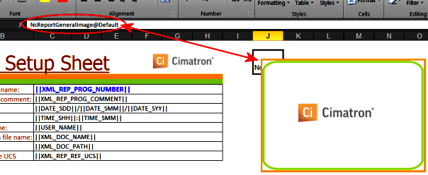
Change the Picture Name in an Excel NC Report template
The picture name must be "NcReportGeneralImage@Default" for the report picture mechanism to load the current screenshot that is captured while the report is created. The following steps explain how to check this.
-
To check the current picture name - Right-click on the picture, select the "Assign Macro…" option.
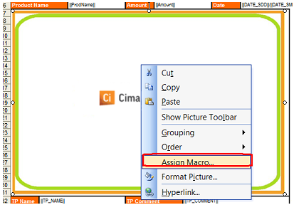
-
The current name will appear in the 'Assign Macro' dialog. In this example it is the string 'Picture6' without the '_Click'.
-
Close the dialog.
-
In order to change the name, click Tools > Macro > Macros… .
-
Set a name to the macro (it can be any string).
-
Click Create.
Paste the lines of code below into the macro editor that was just opened:
Dim sh As Shape
For Each sh In ActiveSheet.Shapes
If sh.Name = "Picture 6" Then
sh.Name = "NcReportGeneralImage@Default"
End If
Next
-
Change the "Picture 6" string (displayed red in the code sample above) to the name you see in step number 2. Note that there MUST be a space between the string "Picture" and the number.
If you are changing a picture name for one of the other available report images: 'ISO' or 'Stock', make sure you change to the appropriate name "NcReportGeneralImage@ISO" or "NcReportGeneralImage@Stock" in the "sh.Name=" argument. -
Run the macro by pressing F5.
-
Close the Macro Editor window.
-
Repeat step #2 to check that the name was changed.
Change the Picture Name in an XLSX NC Report template
Changing a picture name in XSLX templates is much simpler than in the XLS templates. In order to have get the picture dynamic and load the captured picture each time a report is created, all that is needed is to type the picture name (without the extension) in the cell where the upper left corner of the picture is located.
Note that once you enter the picture name, it is saved as a hyperlink (because of the "@" sign); the hyperlink should be removed.
Tools Report Template - Excel
A Tool Report template is basically the same as a NC Setup Report template only that it is tool-oriented rather than procedure- oriented. Here the information in the Body section is repeated for each tool, rather than for each procedure.
The same three sections (Header, Body and Trailer) exist. The structure of the Body area is slightly different than with the NC Setup Report. The body section contains only one row range for tools, which is duplicated repeatedly for each tool in use throughout the reported program.
Since the tools report is in fact derived from the NC Setup Report, the tools are listed by the order in which they were used, not according to their magazine number.
Note: Tools are differentiated according to magazine number not by tool name. So if two different tools are assigned the same magazine number, the information of the second tool overwrites the information of the first tool with that magazine number.
NcReportImage.xml
General Structure
The NCReportImage.xml file is a standard XML file that can be edited with either a regular text editor or any XML specific editor.
Each available report is a branch in the ReportList section. Each available picture is a branch of its corresponding Report.
Editing the File
For every report there is a section that begins with <Report Name = "xxxx"> and ends with </Report>. In this section each available picture is defined by its name and dimensions.
|
NcReportImage.xml Demo Report section |
|
|
Text Editor |
XML Editor |
|
|
|
In this area the dimensions of the picture frame are defined. Change, if necessary, only the frame size.
<NcReportDefaultImage>
<Width>300</Width> Width Definition
<Height>200</Height> Height Definition
</NcReportDefaultImage>
In the next area the pictures that can be created with the Capture Report Images function are defined. One or more pictures can be defined in this way (or no pictures at all).
<PicturesList> Begin List
<Picture Name = "ISO"> Begin definition for ISO
<Width>318</Width> Width
<Height>279</Height> Height
</Picture> End definition for ISO
<Picture Name = "Stock">
<Width>222</Width>
<Height>413</Height>
</Picture>
</PicturesList> End List
Creating More Reports
More than one type of report can be made available at the time of report creation. Create another template file (in MHT or Excel format) according to the desired style and content. Save it in the folder …\Program\NC\Customized Reports. Edit the XML file to include a new branch in the ReportsList section with the name of the new report. Under that branch define the pictures that you want to appear with the report. This can be repeated as many times as is necessary.
For example, to add another report called "Electrode", add a new branch in the ReportList section starting with <Report Name = "Electrode"> and ending with </Report>. In between, define the Default and the Pictures from the List as desired, as shown below in red:
<ReportsList>
<Report Name="Demo">
<NcReportDefaultImage>
<Width>300</Width>
<Height>200</Height>
</NcReportDefaultImage>
<PicturesList>
<Picture Name="ISO">
<Width>318</Width>
<Height>279</Height>
</Picture>
<Picture Name="stock">
<Width>222</Width>
<Height>413</Height>
</Picture>
</PicturesList>
<NcReportProcedureImage>
<Width>120</Width>
<Height>80</Height>
</NcReportProcedureImage>
</Report>
<Report Name="Electrode">
<NcReportDefaultImage>
<Width>300</Width>
<Height>400</Height>
</NcReportDefaultImage>
</Report>
</ReportsList>
Typical Procedure and Tool Variables
An almost unlimited number of variables are available for the NC Setup Report. These include the parameters of the procedure as well as those of the tools (including shaft and holders). The following is a list of the typical variables. Some variables (displayed in red below) can be used in the Body as well as the Trailer sections.
|
Typical Header Variables |
|
|
Variable |
Use |
|
||PART_NAME|| |
Name file name (ELT file) |
|
||XML_DOC_PATH|| |
Path (ELT file) |
|
||XML_REP_PROG_NUMBER|| |
program number |
|
||XML_REP_PROG_COMMENT|| |
program comment |
|
||DATE_SDD|| |
Date - Day |
|
||DATE_SMM|| |
Date- Month |
|
||DATE_SYY|| |
Date - Year |
|
||PART_NAME|| |
User Name |
|
Typical Body Variables |
|
|
Variable |
Use |
|
||TP_NAME|| |
TP Name |
|
||TP_COMMENT|| |
TP Comment |
|
||PROC_NAME|| |
Procedure Name (short) |
|
||PROC_LONGNAME|| |
Procedure Name (long) |
|
||PROC_UCSNAME|| |
|
|
||PROC_COMMENT|| |
Procedure Comment |
|
||XML_CLEAR_PLANE|| |
Clearance Plane |
|
||SPIN_SPEED|| |
Spindle Speed |
|
||MCH_FEED|| |
Machine Feed |
|
||XML_SURF_OFF|| |
Surface Offset (general) |
|
||XML_SURF_TOL|| |
Surface Tolerance |
|
||XML_H_STEP|| |
Horizontal Step |
|
||XML_V_STEP|| |
Vertical Step (general) |
|
||XML_ELECTRODE|| |
Electrode Machining (Yes/No) |
|
||XML_ELEC_SPARK_3D_GAP|| |
Spark Gap + 3D Orbit |
|
||XML_ELEC_PLAN_GAP|| |
Orbit Planar Gap |
|
||CYC_PECK|| |
Drill Cycle Peck |
|
||CYC_DWELL|| |
Drill Cycle Dwell |
|
||CYCLE_1...12|| |
Drill Cycle |
|
||TOOL_NAME|| |
Tool Name |
|
||TOOL_CMNT|| |
Tool Comment |
|
||E_TOL_TYPE|| |
Tool Type (see below) |
|
||DIAMETER_|| |
Tool Diameter |
|
||TOOL_RAD|| |
Tool Radius |
|
||TOOL_NUM|| |
Magazine Number |
|
||TEETH_NUM|| |
Number of Teeth |
|
||CLEAR_LENG|| |
Clear Length |
|
||CUT_LENGTH|| |
Cutting Length |
|
||XML_MIN_CLEAR_LEN|| |
Minimum Clear Length |
|
||TOOL_TOTAL_LENGTH|| |
Total Tool Length |
|
||CON_ANG|| |
Tool Conic Angle |
|
||TOOL_ANGLE|| |
Tool Tip Angle |
|
||SHANK_CON|| |
Spindle Conic height |
|
||SHANK_TOT|| |
Shank Total height. |
|
||SHANK_BOT|| |
Shank Bottom diameter |
|
||SHANK_TOP|| |
Shank Top diameter |
|
||HOLD_CON01|| |
Holder Conic height (holders 1 to 10) |
|
||HOLD_TOT01|| |
Holder Total height (holders 1 to 10) |
|
||HOLD_TOP01|| |
Holder Top diameter (holders 1 to 10) |
|
||HOLD_BOT01|| |
Holder Bottom diameter (holders 1 to 10) |
|
||X_MAX|| |
Maximum X |
|
||X_MIN|| |
Minimum X |
|
||Y_MAX|| |
Maximum X |
|
||Y_MIN|| |
Minimum Y |
|
||Z_MAX|| |
Maximum Z |
|
||Z_MIN|| |
Minimum Z |
|
||AIR_TIME|| |
Rapid Motion Time |
|
||FEED_TIME|| |
Cutting Motion Time |
|
||TOTAL_TIME|| |
Air Feed Time |
Note: The variables displayed in red give the totals for the entire file when used in the Trailer.
E_TOL_TYPE values:
0 – Ball cutter
1 – Bull nose cutter
2 – Flat cutter
3 – Drill
4 – Reamer
5 – Tap
6 – Center drill
7 – Lollypop cutter
8 – Slot mill (full radius)
9 – Slot mill (sharp corner)
10 – Slot mill (corner radius)
11 – Dove mill (full radius)
12 – Dove mill (sharp corner)
13 – Dove mill (corner radius)
14 – Counter sink
|
Typical Trailer Variables |
|
|
Variable |
Use |
|
||PROC_CNT|| |
Number of procedures (with Auto-Drill also number of tools and orientation changes) |
|
||TOOL_CNT|| |
Number of Tools |
|
See also Body Variables marked in red |
|
Additional Variables & Information
More variables and information can be found in this Online Help in the following sections:
Customized adaptation / extension of the file "gpp2-xml.ini ":
The file "gpp2-xml.ini" is used to map variables that are available through the XML mechanism, to be used in the report (or any other GPP2 post processor). These variable names all have "XML _ " at the beginning.
The file "gpp2-xml.ini" can be adapted by the customer at his own responsibility (i.e. he may need to update the file due to future version changes). This enables the user to access practically every parameter of any procedure and output the value to the NC Setup Report.
Posting with a GPP2 post processor outputs a temporary XML. This file contains all the parameters of each posted procedure. For example, the XML file for a 2 ½ X Profile - Closed Contour contains the following section for Contour Tolerance:
To add the parameter to the NC Setup Report, the following line should be added to the "gpp2-xml.ini" file:
25, "Contour Tolerance", XML_CON_TOL, 1
ID(1) Name (2) Variable name(3) Format Number(4)
Taken from the XML file
Exactly how it appears in the menu (translated name for translated menus)
User defined. Must start with "XML_"
According to the GPP2 standard:
|
Format Name |
Format Number |
Format Name |
Format Number |
|
CHARACTER |
0 |
USER_3 |
10 |
|
COORDINATES |
1 |
USER_4 |
11 |
|
ANGLES |
2 |
USER_5 |
12 |
|
FEED |
3 |
USER_6 |
13 |
|
SPINDLE |
4 |
USER_7 |
14 |
|
DWELL |
5 |
USER_8 |
15 |
|
SEQUENCING |
6 |
USER_9 |
16 |
|
TOOL |
7 |
USER_10 |
17 |
|
USER_1 |
8 |
REAL |
18 |
|
USER_2 |
9 |
Important: The variable name must include "_" and should not include spaces!
User defined variables:
In addition to the above mentioned System and XML variables, the NC Report also supports user-defined variables. These variables should be used in the post regularly, according to GPP2 rules. In order for them to be available for the report, they should be declared as such in the declaration area of the post, using the statement REPORT_VARS. For example:
REPORT_VARS <variable name>;
Troubleshooting MHT Format Templates
MHT format templates are extremely sensitive to formatting issues. Even minor modifications can sometime cause some problems. The following are 2 common examples.
Example 1
The report is output but in one place the variable name is output instead of its value.
In order to fix this you should open the template for editing in a text editor (Notepad will do). Search for the variable name – in this case "ProcedureFeed".
You might find it looking like this: ||></span>ProcedureFeed></o:p></span||. Since no spaces or other symbols are allowed between the variable name and the "||" symbols on both sides, this means that all the characters marked in red above are actually "junk" that should not be there. Note that the redundant characters can be any, not necessarily those that are marked in red above.
Delete these redundant characters so that the result will look like this: ||ProcedureFeed||. Save and close the text editor. Run the report again - this should solve the problem.
Example 2
The beginning of the report looks as expected. However, from a certain point on it looks disrupted. Key strings are shown and variable names appear instead of their values.
The problem is most probably located in the first key string that is shown. Open the template for editing in a text editor and search for the first key string shown. As seen in the above picture, you should search for "tlpath".
The proper way to have the key string is as follows:
<<tlpath>> – it should have << before it and >> after it. No spaces or other characters are allowed in-between.
You should expect to have the first shown key string with some redundant characters, something like the following characters in red: <<<span style=3Dtlpath</span><>>
Note that the redundant characters can be any, not necessarily those that are marked red above. These redundant characters need to be deleted.
Setting an Image in MHT while Editing with Office 2007 or Newer
In Microsoft Office 2003, inserting an image with the default name (NcReportGeneralImage@Default.jpg) in the template, was enough to make it recognize the captured image and automatically replace the image in the report.
Unfortunately, due to Microsoft's changes in Office 2007 (and newer), this is no longer enough. Some additional steps need to be done in order to make it work properly.
After the image is inserted to the template (as in Office 2003) do the following:
Activate the Selection Pane under Page Layout.
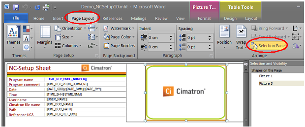
Click on the image and identify its name in the pane on the right.
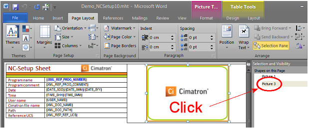
Rename to remove the space.
Close and Save.
Open the template with a text editor (Notepad).
Search for the picture name as you have renamed it.
Look for the string o:title=3D"" a few lines further down.
Insert the default report picture name "NcReportGeneralImage@Default" between the quotation marks, right after the "3D".
Save and close. The report image should now function as expected.
|