NC Setup Report  : Standard

Access: Open this function from one of the following locations:
-
Select NC Process > Post & Report > NC Report from the menu bar.
-
Click the NC Report button
in the NC Guide. -
Click the NC Report button
in the Job
Manager. -
Right-click on an item in the Process Manager, or anywhere in the graphics window when no procedure is active, and select NC Guide Commands > NC Report from the popup menu.
The NC Report is a file that provides various information about a set of selected procedures. This information includes details about the project and provider, as well as toolpaths, procedures (including multi-cutter information), and parameters.
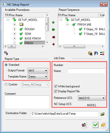
The Standard report type is a fully customizable, easy to manage report. A number of output formats are available and, depending on the chosen file format, the generated report will be opened in the appropriate viewer (see Output Format below for the list of supported output formats).
The Standard report only supports procedures containing motions.
The default Standard report type is a fully customizable, easy to manage MHT report (see below for additional output formats). The Standard report only supports procedures containing motions.
|
|
Set the following:
Note that if the Standard report type is selected, the Program Data parameters are displayed:
|
Notes:
-
Report images (views) are automatically resized to prevent dimension overlapping between the views.
-
The image appears in the report as it is displayed in the graphics display area. For example:
-
If a UCS appears in the graphics display, it also appears in the report image.
-
If the images in the graphics display is shaded, it also appears shaded in the report image.
-
-
If the Template Name = Elec, the font size of the dimensions in the report image can be controlled using the Picture Font Size parameter. The default value is the current font size. The last used font size is kept for subsequent use.
-
All dimensions in ISO views and the middle dimension of side views do not appear in the report image.
When you select the Standard report type the following options/fields are displayed:
|
Select the output format for the report from the dropdown list of options. Depending on the chosen file format, the generated report will be opened in the appropriate viewer (see the notes below). The following formats are available;
File Format Information for ReportsFile Format Information for Reports Definitions of the available report file format templates are listed below. The last used save type is retained for the next save.
For additional information on 3D PDF, see Publish to PDF. Notes:
|
|
|
Template Name |
Select the required template for the report from the dropdown list of options. The available templates are based on the option selected in the Output Format field. The Electrode option in the dropdown list enables you to create an Electrode NC Report. |
|
Comment |
Enter a comment for this report if required. |
|
Destination Folder |
|
|
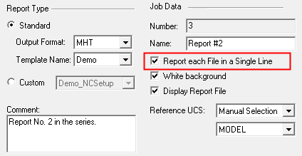
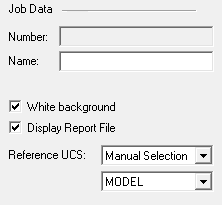
Number |
The Job ID Number is automatically generated when invoking the Job Manager. This number is displayed in the Post Process dialog and also in the NC Report dialog when they are invoked from the Job Manager. |
|
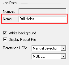
Name |
The Job Name can be entered in the Post Process and NC Report dialogs. This name is used in the Job Manager dialog where it can be edited (the name can also be defined in the Job Manager itself). Enter a report name if required. This defines the file names of the report files written into the folder specified in the Destination Folder field in the NC Setup Report dialog. This name is used in the Job Manager dialog where it can be edited. If no name is entered, the report file name is the Post name: If a name has been entered, the report file name is: For additional information, see Execution below. |
|
Picture Font Size |
The font size of the dimensions in the report image can be controlled using the Picture Font Size parameter. The default value is the current font size. The last used font size is kept for subsequent use. This parameter is displayed when the NC Report Template Name field is set to Elec (see Electrode NC Report). |
|
Report each File in a Single Line |
Select this checkbox to show each post output file (created in the last Post Processor session that had created any output) as a single line in the NC Report. This parameter is displayed when the NC Report dialog is invoked from the Job Manager.
|
|
White Background |
Set the background color. This can either be white or the default color
in the current display.
When this checkbox is ON  ,
a white background is set for this operation. ,
a white background is set for this operation. |
|
Display Report File |
Select the checkbox to immediately display the NC Report when you exit the dialog by pressing OK. |
The following parameter appears in the NC Report (Standard) and also in GPP2:
|
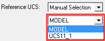
Reference UCS |
This field displays the settings as defined in the NC Setup; this can be changed if required.
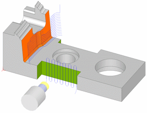
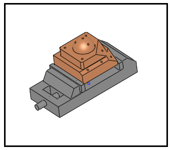
Define the Reference UCS on which the current operation is to be based from a dropdown list of all the UCSs in the current ELT file. This Reference UCS enables you to define a different UCS as required; for example, when a different clamping situation is necessary, typically "Machining from TOP" and "Machining from BOTTOM". In the example below, the orange surface will be machined from above and the green area from the side. Because it is machined from another orientation, the green surface toolpath has different motion limits, which are based on its own separate UCS.
The Reference UCS is also important in the posting process where it defines the reference point and reference axes direction for the whole posting process. All other UCS's and tool points are defined relative to the Reference UCS. The following Reference UCS options are available from the dropdown list:
For additional information, see GPP2:
Reference UCS and the posting process.
|
A black frame is displayed in the graphics area. This frame defines the contents of the image that will appear in the header section of the NC Report. The size of the frame is defined in the template and cannot be dynamically changed; however, you can use the usual Cimatron view manipulation functions to define the contents of the frame.
If required, additional pictures can be added to the report after they have been captured using the Capture Report Images tool.
Execution
Once you have defined the appropriate settings in the NC Setup Report dialog, press OK ![]() to generate the report. The following occurs:
to generate the report. The following occurs:
-
Two files are written into the folder as specified in the Destination Folder field in the NC Setup Report dialog.
<file_name>.Setup.<suffix>
This file contains the setup report consisting of details about the project and provider, as well as procedures and parameters.
<file_name>.Tools.<suffix>
This file contains the tool report consisting of details about the various tools used.
The <suffix> of the file names above depends on the Output Type selected in the NC Setup Report dialog:
-
HTML = suffix MHT
-
PDF = suffix PDF
-
Excel = suffix XLS
In the examples below, the MHT suffix is used.
The <file_name> of the file names depends on whether a name has been specified in the Name field of the Program Data parameters.
If no name is entered, the report file name is the Post name: <Post_name>.Setup.mht.
The post name consists of the Cimatron file name, the toolpath name, and the post.
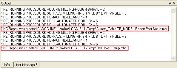
In the example below (where no name is entered), the file names (in this case) would be:-
Cutters_Table.TP_MODEL.Report-Post.Setup.mht
-
Cutters_Table.TP_MODEL.Report-Post.Tool.mht
If a name has been entered, the report file name is: <Name>.Setup.mht.
In the example below, the file names would be:
-
Drill Holes.Setup.mht
-
Drill Holes.Tools.mht
-
-
The image displayed in the NC Report (captured within the black frame in the graphics area) is saved in a file named:
NcReportGeneralImage@Default.jpg.The captured images are saved in the following folder:
...\ProgramData\Cimatron\Cimatron\2026.0\Data\Nc\Report_Images\<elt_file_name> -
If the Display Report File parameter has been selected, the NC ReportNC Report (<file_name>.Setup.mht) is immediately displayed.
The NC Report is divided into three distinct areas:-
Header - containing the program information, file and user name, and the captured picture.
-
Body - containing all the procedure data.
-
Trailer - containing motion limits and general statistics.

-
- The creation of the *.Setup.* files is also reported in the Output Pane.
-
The example below shows the NC Report was created twice; once with the Name field empty (hence the post name file: Cutters_Table.TP_MODEL.Report-Post.Setup.mht) and once with the Name field filled - the file Drill Holes.Setup.mht.